
Timers are very useful in many household applications, in the laboratory, and even in schools for experiments. The circuit we describe here is the most basic in this type of application: a timer with the famous 555 that turns off a load and itself after a time interval. The load depends only on the relay used and the maximum time is determined by the leaks of the electrolytic capacitor used, usually limited to something around 1 hour.
Among the possible applications for this circuit, we suggest the following:
* Turn off TVs and devices automatically if the player has the habit of sleeping with these connected devices.
* Automatically turn off heaters and electric cookers after a set time, avoiding the burning of food.
* Automatically turn off light bath systems for developing photos or other chemical processes.
* Automatically light balconies, gardens or hallways after the drive.
Other applications can easily be imagined by the reader, especially those involving industrial machines and automatisms. Even robotics and mechatronics circuits can use this automatic shutdown system in some process.
HOW IT WORKS
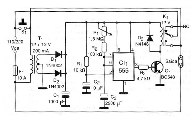
The circuit uses the most appropriate component for the realization of a timer: the integrated 555 timer. In the monostable configuration, when the trigger input corresponding to pin 2 is grounded for a moment, the output corresponding to pin 3 goes to the high level.

With the circuit triggered, the output at high level saturates the relay that closes its contacts. In these conditions, even if switch S1 is released, the relay contacts ensure that the load continues to receive power.
The relay will remain closed for as long as the 555 output is at the high level. This depends on both the P1 setting and the C3 capacitor value. For practical reasons already mentioned, the capacitor can´t be larger than 2 200 ?F and the potentiometer larger than a 2.2 M which limits the activation time to approximately 4,800 seconds resulting in something around 1 hour and a half .
In practice, it is not recommended to reach as much, because the circuit tends to instability. However, the reader may be lucky enough to use a really good quality capacitor with few leaks, and this does not happen.
The accuracy of the timing depends only on the circuit setting. Using a stopwatch or common clock it is possible to establish a scale with good accuracy for the potentiometer. When the timer runs out, the 555 output goes low and the transistor cuts off the relay supply, which opens its contacts.
The result is that both the load and the circuit itself fail to receive the power by switching off.
For a new timing, the switch S1 must be pressed again for a moment. It may take a few seconds for C2 to download. If this takes too long, we can connect a 47 k (not smaller) resistor in parallel with this capacitor.
The controlled load depends only on the capacity of the relay contacts. Common types with chains between 6 and 10 amps serve to control most common household appliances, except those with high power, such as room heaters and air conditioners.
ASSEMBLY
In figure 1 we have the complete diagram of the minuteria.
In figure 2 we have the complete assembly, including the arrangement of the components on a printed circuit board.
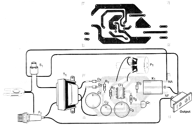
The design of this board is for a G relay, but if the reader uses another type, which is perfectly possible, you should check that the terminal arrangement needs to be changed. Any 12 V common relay with a drive current of up to 50 mA will be used for this design.
The input transformer has primary winding according to the power and secondary grid of 12 + 12 V with a current of at least 250 mA.
Note that although higher voltage is obtained after rectifying and filtering, the relays used normally allow for voltages slightly above the nominal ones in operation, without endangering them.
The other components have the minimum voltage, tolerance and dissipation specifications given in the material list. In the assembly, we draw the reader's attention to two important points:
The first is that the unit works on the mains power supply and is therefore subject to dangerous voltages which can cause shock and short. Thus, utmost care should be taken with the insulation. We recommend that the box used is not made of metal to reduce the likelihood that any live point will touch it.
The second is that the wires that will drive the most intense main currents have thickness compatible with the function. A protective fuse at the entrance is important to ensure the integrity of the apparatus and the power network itself in case of short.
We also suggest to the reader that if you want, connect a series LED with a 2.2 k resistor to the output of the rectifier diodes of the source, so that you have a visual indication of the operation if this is important in your application.
TEST AND USE
To test the appliance, simply connect it to the mains and the output of a load that can be easily monitored, such as a standard 5 to 100 W light bulb (eg a lamp). Set P1 initially to the lowest resistance position (shorter time), and press S1 for a moment.
The relay must dock with the power of the lamps, which will light up. Even if you release S1, the lamp should remain on. After some time, which depends on the setting of P1, the lamp will turn off.
Once the device is working, you can use it. For this, simply connect it to the power grid and, at its output, the load to be controlled. Set the desired time and press S1 for a moment.
Note that P1 must always be set before S1 is pressed. To reset and get a new timing it is convenient to wait a bit for the C3 capacitor to completely discharge.
For this to be done instantaneously, a discharge switch in parallel with this component may be included. Never use the appliance with a load higher than the one supported by the relay contacts.
Semiconductors:
CI1 - 555 - integrated circuit, timer
Q1 - BC548 or equivalent - NPN general purpose transistor
D1, D2 - 1N4002 or equivalent - rectifier diodes
D3 - 1N4148 or equivalent - general purpose diode
Resistors: (1/8 W, 5%)
R1 - 10k
R2 - 100k
R3 = 4.7 k
P1 - 1.5 or 2.2 M - potentiometer
Capacitors:
C1 - 1000 ?F / 25 V - electrolytic
C2 - 10 ?F / 25 V - electrolytic
C3 - 2 200 ?F / 16 V - electrolytic
Several:
T1 - Transformer with primary according to local and secondary network of 12 + 12 V with current from 200 mA - see text
K1 - 12 V x 50 mA relay - see text
S1 – Push Button NA (Normally Open)
F1 - 10 A - fuse
Printed circuit board, mounting box, power cable, fuse holder, output socket, potentiometer knob, wires, solder, etc.


