

With a tap on the touch switch we turn on the load and with a new tap we turn it off. This is the purpose of this circuit which, using a relay, is totally isolated from the power grid. Appliances and electronic appliances can be easily controlled either from a pressure switch or from normally open type sensors.
As an example of application for this control we can mention sound equipment that can be connected together from a touch on the switch and off with a new touch. In the standby condition the consumption of the appliance is quite low which allows it to be permanently connected without appreciable increase of the electricity bill.
HOW IT WORKS
The base of the circuit is a bistable designed around two ports of a 4093B integrated circuit. These ports are connected as inverters in the configuration shown in figure 1.
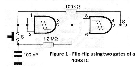
When we tap S1 the circuit works as an oscillator where the frequency is given by R1 and C3. In other words, during the short actuation of S1 we have a state change at least once in the logic level of the first port output and consequently the second port. However, the resistor R2 feeds the circuit so that by releasing S1 the logic level appearing at the output of the second port locks the circuit, which remains in this way until a new tap on S1 produces a new change and therefore a new locking.
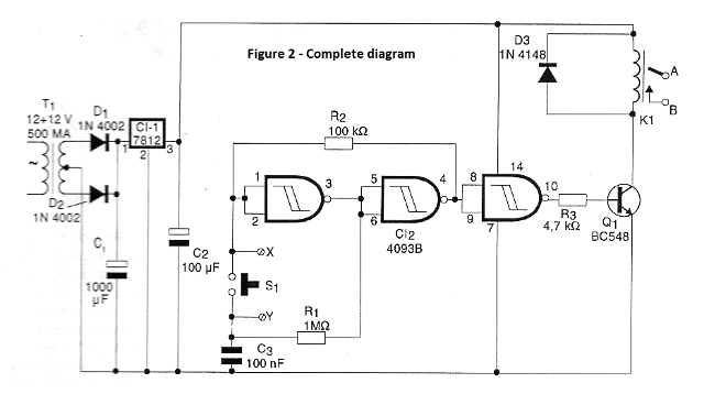
The logic level of the output of the biestable is applied to a third port of the same integrated circuit which functions as the inverting amplifier by driving a transistor which charges the relay coil. In this way, each trip of the S1 switch has the state change of the transistor that goes from saturation to the cut and vice versa, activating the relay.
In our version the circuit is powered by 12 volts from a source stabilized from the power grid but nothing prevents changes to be made for operation with other voltages provided that an appropriate relay is used. It is interesting to note that, given the drive configuration, several normally open type pressure switches may be connected in parallel to control this circuit.
ASSEMBLY
In figure 2 we have the complete diagram of our electronic control.
The arrangement of the components on a printed circuit board is shown in figure 3.
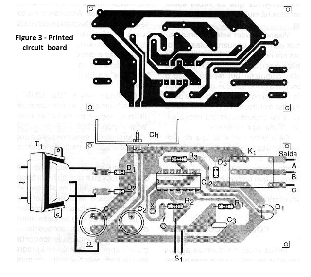
It will not be necessary to equip the heat regulator voltage regulator circuit (CI-1) given the low current consumption. The relay can be the G1RC2 or equivalent of 12 volts with 50 mA drive current and 10 A contacts. The transformer has primary winding according to the power and secondary grid of 12 + 12V with current from 500 mA.
C1 must have a working voltage of at least 25V and C2 of at least 16V. The X and Y points are recommended for connection of sensors or other switches for parallel drive. The resistors are all 1/8W or larger and C3 can be both polyester and ceramic.
TEST AND USE
To test the device simply connect it to the power supply and press S1. The relay should change state. In figure 4 we have an example of application in the control of a lamp.
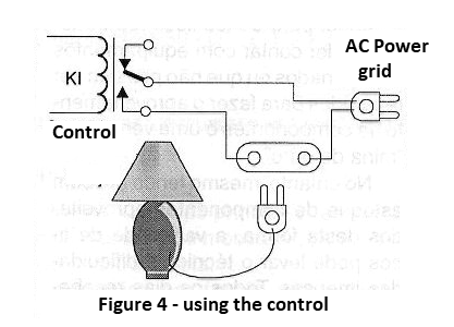
Please note that the controlled loads are connected to the mains and proper precautions must be taken against shocks.
Semiconductors:
CI-1 - 7812 - integrated circuit, voltage regulator
CI-2 - 4093B - CMOS integrated circuit
Q1 - BC548 or equivalent - NPN general purpose transistor
D1, D2 - 1N4002 or equivalent - silicon diodes
D3 - 1N4148 - general purpose diode
Resistors: (1 / 8W, 5%)
R1 - 1 M ohm
R2 - 100 k ohm
R3 - 4.7 k ohm
Capacitors:
C1 - 1000 uF / 25V - electrolytic
C2 - 100 uF / 16V - electrolytic
C3 - 100 nF - ceramic or polyester
Several:
T1 - transformer with primary according to the local and secondary network of 12 + 12V with at least 500 mA
K1 - 12V relay - see text
S1 - NA switch - see text
Printed circuit board, mounting box, wires, solder, etc.


