
There are several types of D / A converters in the form of integrated circuits with excellent performance and inputs fully compatible with PC ports. One such integrated is the Motorola MC1408 that can operate with the 8 parallel port outputs of any PC and provide output voltages over a wide range of externally adjusted values.
What we describe in this article is an application of this integrated circuit that provides output voltages of -10 to + 10V when the logical levels of the parallel port range from 0000 0000 to 1111 1111.
With any control program, it is possible to place 256 different voltages in the indicated range and thus obtain control of many types of external circuits. The circuit operates with 5V single and 10V symmetrical voltage and the use of an operational amplifier as buffer allows a good isolation of the PC in relation to the controlled circuit.
HOW IT WORKS
The basis of this design is the MC1408 integrated circuit consisting of an 8-bit digital-to-analog (D / A) converter that provides an output current that is the linear product of an 8-bit digital word by an analog input voltage.
The accuracy of this circuit is large with a maximum error of 0.19% over the entire operating temperature range. The fixing time is 300 ns and the inputs are compatible with MTTL and CMOS logic. The voltage supply range is between 5 and 15 volts.
In figure 1 we have the block diagram of this integrated circuit.

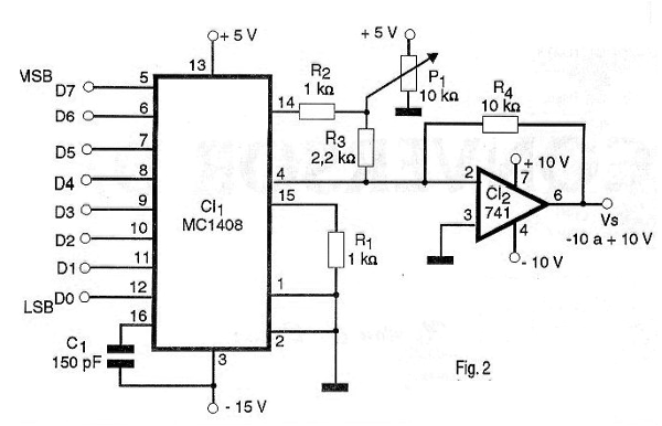
In our project the digital inputs are connected directly to the serial port of a PC. The reference signal is provided by the trimpot P1 and an operational amplifier acts as a buffer in order to determine the variation of the output voltages using symmetric source. The gain of this amplifier is determined basically by the 10 k resistor between the inverting input and the output.
The values of the components used in this application are typical but changes may be made depending on the applications. An external symmetrical 10 V source should be used for the operational amplifier and a 5 V source for the converter.
ASSEMBLY
In figure 2 we show the complete diagram of the D / A converter.
The arrangement of the components on a printed circuit board is shown in figure 3.
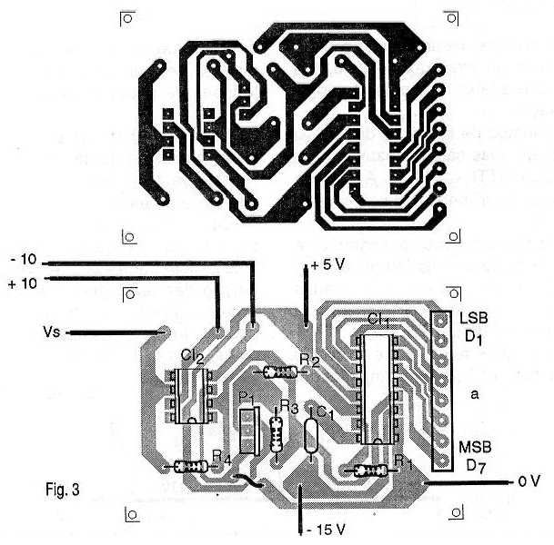
The MC1408 integrated circuit is supplied in a 16-pin DIL housing. For added assembly safety, it will be interesting to install this integrated circuit in a socket.
The resistors are 1/8W and the capacitor can be ceramic. For connection to the PC a common printer cable can be used that has removed the connector from the side of the printer and the wiring connections are made to the corresponding points on the printed circuit board. For the output we can use a common cable or even a pair of terminals depending on the type of application you have in mind.
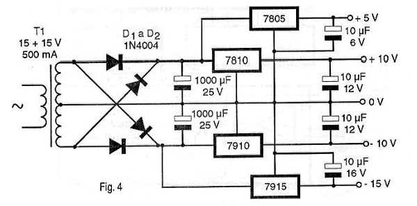
A complete power source containing 5V positive and 10-0-10V symmetrical output is shown in figure 4.
The circuit may be installed in a small plastic housing or if used in demonstrations it may be mounted in a protoboard.
ADJUSTMENTS AND USE
The only adjustment to be made is that of the reference voltage which should be 2 V.
Once the adjustment has been made, the reader must prepare a program (in the language that he or she thinks best) and provide all possible values ??in the parallel outputs. Remember that these are the data lines of the serial output. Once the program is done and the device is switched on, just check if it works with the connection of a multimeter to the output of the circuit.
Note that the output voltage is measured with respect to the 0V reference point of the symmetric source.
Semiconductors:
CI-1 - MC1408 - D / A Integrated Circuit - Motorola
CI-2 - 741 - integrated circuit - operational amplifier
Resistors: (1/8W, 5%)
R1, R2 - 1k ohm
R3 - 2.2 k ohm
R4 - 10 k ohm
P1 - 10 k ohm – trimpot
Capacitor:
C1 - 150 pF - ceramic
Several:
Printed circuit board, printer cable, power supply, wires, solder, etc.
8-bit COMMON A / D AND D / A CONVERTERS
A / D
MC14433P - 3 1/2 bit resolution with 40ms conversion time and +5 and +8V supply voltages.
MC14447P - 8-bit resolution with 300ms conversion time and -5- and +8V supply voltages.
MC14559P - 8-bit resolution with symmetrical power from 3 to 18 V.
ADC0803 - 8-bit resolution with conversion time of 100 us and 5 V power supply
ADC0808 - 8-bit resolution with conversion time of 100 us and 5 V supply voltage.
ADC0809 - 8-bit resolution with conversion time of 100 us and 5 V supply voltage.
ADC0817 - 8-bit resolution with 16 channels of multiplexing; conversion time of 100 us and power of 5 V.
ADC0820 - Conversion time of 1.18 us and power of 5 V.
D/A
MC1408P - 8-bit resolution and fixture time of 300 ns. Supply voltage of +5 and -15 V.
DAC08 - High speed 8 bit resolution. Fixing time of 150 ns and symmetrical power of 4.5 to 18 volts.
DAC0800 - 8-bit high-speed resolution. Fixing time of 100 ns and symmetrical supply voltages of 4.5 to 18 volts.
DAC0808 - 8-bit high-speed resolution. Fixing time of 150 ns and symmetrical supply voltages from 4.5 to 18 V.
DAC 0830 - 8-bit resolution and 1-sec. 4.5 to 18 V symmetrical supply voltages.


