The UMC Korean integrated circuit UM5003 (Not easy to fund these days) is presented in two versions: UMC5003-01 which has the programmed sounds of lion, elephant, seal and cuckoo and in the version UM5003-02 that has the sounds of horse, cow, sheep and canary.
Although the component market in our country is problematic and we can not always say that such integrated circuits can be easily found, the reader may be lucky enough to find it in one of the possible versions and thus the project we describe can be carried out with ease.
The choice of sound that the circuit will reproduce depends on the programming that can be done either by means of a jumper or from a selector switch depending on the application. The circuit can be powered by voltages from 2.5 to 4.5 Volt and directly excites a small speaker using only a common transistor for this.
When the circuit is activated by pressing a key (or sensor) depending on the application, the sound of the bug corresponding to the programming is issued and at the same time a led (optional) lights up. The few components used guarantee a compact assembly that can be installed in toys and other applications.
HOW IT WORKS
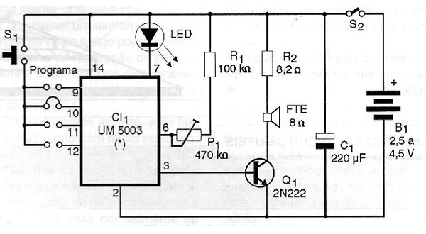
The integrated circuit UM5003 does everything because it contains the sounds programmed according to the version. To select the desired sound, according to the table below, simply connect the push button S1 to the corresponding input:
Input 9 / UM5003-01 = Lion / UM5003-02 = Horse
Input 10 / UM5003-01 = Elephant / UM5003-02 = Cow
Input 11 / UM5003-01 = Seal / UM5003-02 = Sheep
Input 12 / UM5003-01 = Cuco / UM5003-02 = Canard
When S1 is pressed for a moment the circuit is triggered and produces the corresponding signal that appears in the output 3 connected to the base of an amplifier transistor. This transistor is charged with a small speaker that reproduces the corresponding sound.
The only adjustment we have is from P1 to the playback speed.
ASSEMBLY
In figure 1 we have the complete diagram of the device that imitates bug sounds.

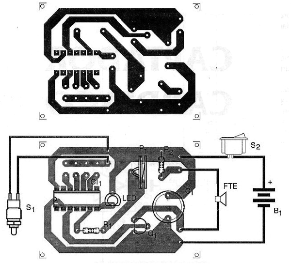
The arrangement of the components on a printed circuit board is shown in figure 2.

The integrated circuit can be soldered directly onto the printed circuit board. The resistors are 1 / 8W and P1 is a trimpot. The speaker is a miniature type of 2.5 to 5 cm and can even be taken advantage of some out-of-use transistor radio.
The transistor admits equivalents and power may come from common or battery cells. In the case of battery, as the consumption is low, the terminals can be welded directly into the power wires.
TEST AND USE
Program the sound of the desired animal by means of a jumper and press S1. By pressing S1 the corresponding sound should be output. Set P1 to make it look as real as possible.
Then just install the device.
Semiconductors:
CI-1 - UM5003 - integrated circuit - see text
Q1 - 2N2222 - NPN general purpose transistor
LED - common red LED
Resistors: (1/8W, 5%)
R1 - 100k ohm
R2 - 8.2 ohm
P1 - 470 k ohm - trimpot
Capacitors:
C1 - 220 uF / 6V - electrolytic
Several:
FTE - 8 ohm x 2.5 to 5 cm - speaker
S1 - Pressure switch NA or sensor
S2 - Single switch
B1 - 2.5 to 4.5 V - batteries or battery
Printed circuit board, mounting box, wires, solder, etc.


