

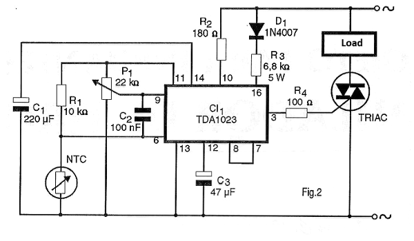
The TDA1023 integrated circuit was specially developed to control the conduction angle of Triacs as a function of the resistance presented by a sensor. If this sensor is an NTC (Negative Coefficient Resistor) we will have an efficient temperature control for a heating element used as a load.
What we propose with this project is a practical application suggested by the dedicated circuit factory itself, which is therefore as reliable as possible. In this application it is possible to control a heating element from a resistive sensor, thus maintaining the temperature of a constant environment.
It should be remembered that in this type of application there is the hysteresis given by the response of the sensor element, depending on its type (thermal capacity, etc.) and its location. Thus, the maintenance of temperature will always be maintained within a certain range and not a value, as suggested in figure 1.
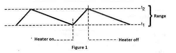
The width of this range, ie the temperatures between which the environment will oscillate depends then on several factors other than the circuit's own performance.
HOW IT WORKS
The sensor element is an NTC which must have a resistance of approximately 10 k ohm in the vicinity of the desired ambient temperature.
Potentiometer P1 makes the adjustment of the power that will be applied to the heating element at the desired temperature, ie it allows to adjust the temperature in the room to the desired value. D1 and R2 provide integrated circuit power directly from the 220 volt power network. Values ??can be changed if the network is 110 volt.
The control signal for the triac is obtained from pin 3, there being a current limiting resistor in series with the gate. The used triac may be the TIC226 for 8 amps which is suitable for most applications where medium power heating elements must be controlled.
The capacitors connected in the integrated circuit serve as both decoupling and filtering.
ASSEMBLY
In figure 2 we have the complete diagram of the thermostat.
The arrangement of the components on a printed circuit board is shown in figure 3.
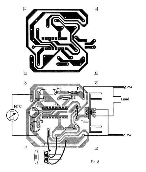
The Triac is TIC226D type for the 220 volt network and must be fitted with a good heat radiator. Electrolytic capacitors must have voltages of 15 volts or more. The resistors must have wattages according to the list of material with attention to R3 which must be of wire with at least 5 watts of power.
The sensor is a low thermal capacity NTC with 10 k ohm at room temperature. This sensor can be connected away from the circuit, but if the cable is too long it must be shielded. P1 is the adjustment potentiometer that can either stay on the control panel or it can be a trimpot built into the assembly itself if the equipment is used in a single temperature.
As the circuit is directly connected to the power grid all care must be taken with the connections mainly of the sensor which should not be exposed. Hazardous or shortcomings may occur if no precautions are taken with insulation.
TEST AND USE
To set the device, you must have a thermometer as a reference and operate on p1 until you reach the desired temperature in the environment in which the system is to be used. Remember that there is a good response time for the NTC to balance its temperature with the environment which requires a good dose of patience in this setting. It should also be remembered that depending on the characteristics of the environment and the sensor it will not be possible to obtain a narrow range of temperature oscillations.
If this band is too wide for your application (say about 5 degrees Celsius) and the reader wants less (2 degrees or less) it will be necessary to re-study the positioning of the sensor. Once the adjustment is done, just use the appliance.
Semiconductors:
CI-1 - TDA1023 - integrated circuit
TRIAC - TIC226D - Triac for 8 amps x 400 V
D1 - 1N4007 - silicon rectifier diode
Resistors:
R1 - 10 k ohm 1/2 W
R2 - 180 ohm x 1/2 W
R3 - 6.8 k ohm x 5 W
R4 - 100 ohm x 1/2 W
P1 - 22 k ohm - potentiometer or trimpot
NTC - 10 k ohms NTC - see text
Capacitors:
C1 - 220 uF / 25 V - electrolytic
C2 - 100 nF - polyester
C3 - 47 uF / 25V – electrolytic
Other: printed circuit board, wires, solder, etc.


