
Strong or unexpected noises always cause scares, especially in very quiet places. If the reader likes to play "parts", mainly electronic and is a beginner, here is an interesting opportunity to highlight their electronic skills.
We describe a simple circuit that consists of a timer that, at the end of the programmed period of a few minutes (1 to 3), produces a loud popping sound in a loudspeaker simulating a shot or even the bursting of a small juniper bomb.
Hide the loudspeaker somewhere in the house and certainly at the time of the "pop" whoever is around, should be a good scare, or at least be intrigued by the source of the noise. The circuit operates with the mains voltage, but its consumption is extremely low. The sound is played on a common speaker that can be obtained from any scrap.
Features:
* Power supply voltage: 110/220 VAC
* Timing: 1 to 3 minutes
* Instantaneous pulse power: 1 to 10 watt
HOW IT WORKS
The capacitor C1 charges slowly through the resistor R1 and the diode D1 which rectifies the mains current. For a capacitor of 10 uF the load through a resistor of 1 M ohms takes a few minutes. The energy that the capacitor accumulates is given by the following formula:
E = 1/2 x C x V x V
For a capacitor of 10 uF (10 x 10-6) with a voltage of 100V we have a charge of:
E = 1/2 x 10 x 10-6 x 10 + 4
E = 5 x 10⁻²
E = 50 mJ (milijoules)
Assuming that in the discharge the pulse lasts 5 milliseconds, then the sound power obtained will be given by:
P = E / t
P = 50/5
P = 10 watt
Then we have a "powerful" burst of sound reproduced on the speaker. To produce the discharge of the capacitor we have a neon lamp connected to the beacon of an SCR. Together we have a resistor R2 and a capacitor C2.
The lamp fires at approximately 80V, and this voltage, given by the delay network formed by R2 and C2, is reached shortly after the voltage at C1 reaches the same value. This means that C1 will be approximately 100V when C2 reaches 80V and the neon light bulb ionizes. With the ionization of the lamp, the SCR trigger conducting the discharge current of the capacitor C1 through the loudspeaker. We then produce a unique sonic pulse of short duration and great intensity.
After discharge of C1, the SCR switches off and, if there is no power interruption, after some time a new pulse will be produced. The value of C1 determines the pulse strength. This component can have up to 10 uF while R1 determines the timing. We should not use resistors larger than 1 M ohms for R1, as electrolyte leakage can impede its charge and thus the trigger.
ASSEMBLY
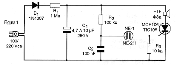
In figure 1 we have the complete diagram of the simulator.
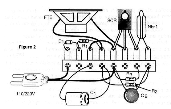
If the assembly is done by beginners it can be done on the basis of a terminal strip, as shown in figure 2.
If the power grid is 220 V the diode must be the 1N4007, but if it is 110V we can use both this type and the 1N4004. The capacitor must have a working voltage of at least 250 V if the network is 110V and at least 400V if the voltage is 220 V. The values of this capacitor can typically be between 4.7 and 10 uF but types can be experienced longer as long as the speaker supports power.
The resistors are 1/8W or larger and the capacitor C2 can be both polyester and ceramic with a minimum working voltage of 100 V.
The neon lamp is the common NE-2H or equivalent and the SCR can either be TIC106 or equivalent for a working voltage of at least 200 Volt (suffix B) if the grid is 110 V or 400 Volt if the grid is 220V (suffix D). This component does not need to be mounted on a heat radiator.
The loudspeaker for best performance should be 10 cm with power of at least 10 watts. Very small speakers taken from transistor radios may burn or present mechanical problems if used to reproduce the loud sounds as the produced by this circuit.
TEST AND USE
To prove it, simply connect the unit to the power grid to save the trigger with the production of the sound pulse. If the pulse does not occur within the anticipated time, this may be due to leaks in the electrolytic capacitor. Reduce R1 to 100k ohms only for testing. If the trip occurs then the capacitor may actually have leakage problems.
If the neon lamp blinks at the end of the expected time, but there is no sound, then the problem may be in the SCR or the capacitor. The neon lamp glows steadily or blinks rapidly, indicating problems with capacitor C1.
Measure the voltage at C1 with the multimeter. If it is too low (below 50V) then there are actually load retention problems with the capacitor. These recommendations are especially important if the capacitor has been taken advantage of by an unused device, as electrolytic capacitors tend to lose their characteristics over time. If the voltage is above 80 volt then the problem may be in the SCR itself that does not fire (open) or still in the neon lamp.
The speaker should be tested beforehand to ensure that it is not the cause of problems either. Larger speakers with heavy magnets provide greater performance in this circuit.
Semiconductors:
SCR - TIC106B or D - or equivalent - silicon controlled diode
D1 - 1N4004 or 1N4007 - rectifier diode
Resistors: (1/8W, 5%)
R1 - 1 M ohm - brown, black, green
R2 - 100 k ohm - brown, black, yellow
R3 - 10 k ohm - brown, black, orange
Capacitors:
C1 - 4.7 uF at 10 uF x 200V or 400V - electrolytic capacitor - see text
C2 - 100 nF x 100 V - polyester or ceramic
Several:
NE-1 - common neon lamp - see text
FTE - 4 or 8 ohms x 10 cm - common speaker
Terminal bridge, power cable, mounting box, wires, solder, etc.


