
The transmitter we teach you to assemble in this article and the receiver can be any FM radio connected to the amplifier used, or else it can be your own sound equipment set to FM frequency free. The transmitter is mounted in a small box that will be attached to the waist of the musician and its antenna is a piece of about 10 cm of wire which gives a range of the order of 20 meters for the system.
In figure 1 we have the complete diagram of the wireless guitar that uses two transistors.

The configuration shown only supports low impedance magnetic pickups or low impedance magnetic microphones. For pickups or "crystal" type microphones, this circuit will not work.
The coil L1 consists of 2 + 2 turns of enameled wire of thickness between 22 and 28 wound on a pencil as reference. The CV trimmer can be any value between 20 and 50 pF and must be set so that the transmitter signal is picked up at a frequency free of the FM range.
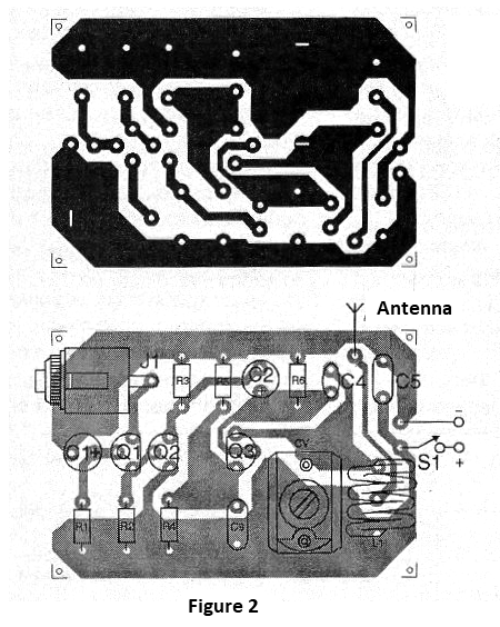
All components are soldered onto the printed circuit board which is shown in figure 2. The antenna should not touch anything, for greater efficiency of the device and in some cases can even be eliminated if the receiver is not more than 5 meters of the musician.
The resistors are all 1/8W and the capacitors must be of the types indicated in the material relation. Do not use polyester types where ceramic is recommended. The input jack J1 must be of the appropriate type for the instrument pickup plug used.
For power supply we have two options: use 4 small batteries with greater autonomy and less reach or use a battery of 9 V with less autonomy but greater range. The only adjustment to be made in operation is to put the receiver into free frequency of the FM band and to act on CV so that the best signal of the transmitter is captured.
Semiconductors:
Q1 - BC549 or equivalent - low noise NPN transistor
Q2 - BC548 or equivalent - general purpose NPN transistor
Q3 - BF494 or BF495 - RF NPN transistor
Resistors: (1/8W, 5%)
R1 - 1 M ohm - brown, black, green
R2 - 2.2 k ohm - red, red, red
R3 - 4.7 k ohm - yellow, violet, red
R4 - 27 k ohm - red, violet, orange
R5 - 12 k ohm - brown, red, orange
R6 - 220 ohm - red, red, brown
Capacitors:
C1, C2-10 uF / 12V - electrolytics
C3 - 2.7 nF at 4.7 nF - ceramic
C4 - 4.7 or 5.6 pF - ceramic
C5 - 100 nF - ceramic
CV - plastic or porcelain trimmer - see text
Several:
J1 - Incoming Check
L1 - Coil - see text
S1 - Single switch
B1 - 6 or 9V - 4 batteries or battery
A - antenna - 10 cm wire (optional)
Printed circuit board, mounting box, battery holder or battery connector, wires, solder, etc.


