
At a science fair or demonstration we can use this little device to show how radio transmitters used in various types of telecommunications services work and even simulate the operation of a radio or cellular telephone.
The signal sent is modulated by a ceramic microphone with high impedance and its power comes from 4 small cells. With the use of a transistor BD135 and increasing the power to 12 volt we can get a longer range by simply reducing R1 to 4.7 k ohm.
HOW IT WORKS
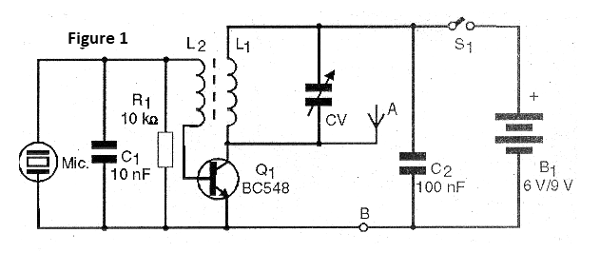
The transmitter is nothing more than an Armstrong blocking oscillator where the frequency is determined by L1 and the capacitor in parallel. To keep the oscillations we have the coil L2 which sends part of the signal to the input of the circuit.
The microphone sends its signal to the base of the transistor in order to modify its polarization and thus to obtain a certain modulation. We can apply other types of signals to the base of the transistor but for this it is necessary to make modifications.
The shortwave designation comes from the fact that the signals are in a frequency band between 3 and 7 MHz that correspond to a wavelength of 100 to 40 meter.
ASSEMBLY
In figure 1 we have the complete diagram of this small shortwave transmitter.
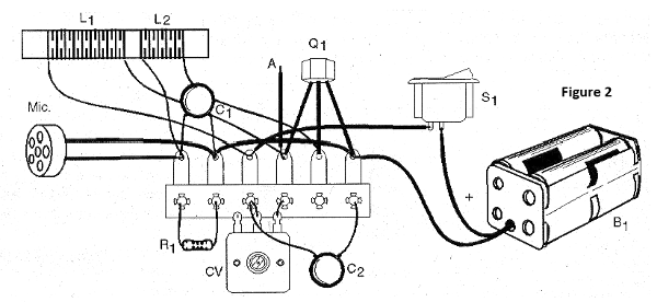
The arrangement of the components on a small terminal strip is shown in figure 2.
The transmitter can be mounted in a small plastic housing with a 50-150 cm telescopic antenna. for greater reach we can connect the point A to an external antenna and the point B to a good earth. The coil L1 is formed by 35 turns of wire 28 wound on a ferrite rod 1 cm in diameter and 10-20 cm in length. L2 is formed by 10 turns of the same wire wound on the side of L1.
The capacitors are all ceramic and R1 is 1/8 W or larger. The CV capacitor can be any variable capacitor of medium or short wave radios with maximum capacitances in the range of 120 to 300 pF.
The microphone must be of the ceramic or crystal type, as other types will not work. An interesting possibility is to use a piezoelectric tweeter from which the small internal transformer has been removed. In this way it functions as a sensitive microphone.
TEST AND USE
To test the unit, connect an out-of-season shortwave radio and CV adjustment near the transmitter signal. If this is not possible, reverse the L2 connection wires. By picking up the strongest signal and speaking in front of the microphone you can evaluate the modulation. To use it will be interesting to place the transmitter in a room and the receiver in another showing how the signals can cross walls because they are radio waves.
We note that in high noise environments, such as those containing a large number of fluorescent lamps, the transmitter signal can be difficult to tune and the range is significantly reduced. In this case, find another location to do the demonstrations. It will be interesting to do on-site testing before fairs or exhibitions to avoid these problems.
WHAT TO EXPLAIN
Show that the small mounted circuit is actually a short-wave transmitter and that its signals traverse solid objects like walls, for example.
Explain that this transmitter, though simple can go very far. Using a very well-sized antenna under favorable conditions it can reach thousands of miles. There is even a radio amateur club that operates exclusively with transmitters of this type and has already made contacts with countries thousands of miles away.
In case the range is not the greatest because the antenna is improper and because you can’t transmit far without having the due license for it.
SUGGESTIONS
By reducing the number of turns we can operate at higher frequencies. For example, with 20 turns we can operate in the range of 10 to 15 MHz. By increasing the number of turns from L1 to 100 we can lower the frequency by making the transmitter operate in the medium wave range.
For external antenna use a piece of wire up to 10 meters in length stretched and not connected at any point other than at point A of the circuit. Mounting a pair of these transmitters and using two receivers can maintain contact between people located in different rooms.
Semiconductors:
Q1 - BC548 or equivalent - NPN general purpose transistor
Resistors: (1/8W, 5%)
R1 - 10 k ohm - brown, black, orange
Capacitors:
C1 - 10 nF (103 or 0.01) - ceramic capacitor
C2 - 100 nF (104 or 0.1) - ceramic capacitor
CV - variable capacitor - see text
Several:
MIC - ceramic microphone - see text
L1, L2 - coils - see text
A - telescopic antenna or wire - see text
S1 – On/Off switch
B1 - 6 or 9 V - batteries or battery
Terminal strip, battery holder, mounting box, ferrite rod, enamelled wire, button for variable capacitor, wires, solder, etc.


