
In a demonstration or work for science fair this circuit can serve to show the difference between conductors and insulators in a very practical way. The important thing is that by the brightness of the LED in the test we can also evaluate the state of components such as resistors, capacitors, coils, lamps, winding coils and transformers, switches, fuses and many others.
The circuit can be powered by two or four small batteries and their consumption is very low. In fact, if the probes are kept separate then it is not necessary to use S1 that the drained current will be practically zero.
HOW IT WORKS
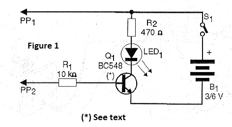
An LED is connected to the collector of a transistor so that it turns on when the transistor conducts the current. In order to conduct the current it is necessary that its base is polarized and this is done through two probes.
When the probes are separated or when some device having a very high resistance, i.e. an insulation, is connected, no current can flow and the transistor does not conduct. Under these conditions the LED remains off. However, when the device or circuit connected between the probes leads to current the transistor is polarized and with that the LED lights up.
For the transistor to conduct, however, the circulating current through the base must have a certain value. Below this value the transistor reduces its conduction and the LED does not light up with all its force. Thus, if the circuit tested has a somewhat high resistance, in the range of 47 k ohm to 1 M ohm, the LED will light but with reduced brightness.
ASSEMBLY
In Figure 1 we have the complete tester diagram.
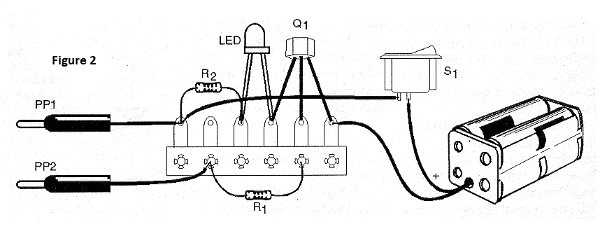
In Figure 2 we have the arrangement of the components on a terminal bridge. The assembly can easily be installed in a small plastic box.
For Q1 we can use any general purpose NPN transistor. The LED can be red or any other color and in its assembly it is necessary to observe its polarity because if it is inverted it does not light, the same thing happens with respect to the transistor and the battery holder.
The resistors are 1/8W or larger and the probes can either be of the type purchased in specialist houses (such as those used in multimeters) as can be improvised with two large nails.
TEST AND USE
To test the unit, simply plug it in after placing the batteries in the holder and touching one probe in the other: the LED should light up at its normal brightness. If the LED lights up with the tips separated or the transistor is turned on or wrong it is burned out.
To use, just touch the probes on the component you want to test. If the component is in any appliance it must be removed or the appliance must be switched off. If the LED lights up in this test the circuit or component has continuity, otherwise it will not. Remember that there are components that are just right when the LED does not light up, such as the capacitors.
It will be interesting to check in the specialized books how the components should behave to know how the tests should be done.
To prove diodes, for example, we have continuity in the sense but not in another; for fuses if there is continuity it is because it is good; for a capacitor if there is continuity (LED lit) it is because it is bad.
WHAT TO EXPLAIN
Take several common materials such as coins, paper clips, graphite, paper, glass, metal objects, etc. Test each of them to demonstrate which are conductors and insulation. Explain the difference between conductors and insulators and differentiate the various materials after testing.
Explain that in the conductors the current flows and so when the test is performed the LED lights up. Have resistors of several values ??in hand to test them with this device showing that the higher the resistance the lower the brightness of the LED.
SUGGESTIONS
The LED can be replaced by a lamp with rated voltage according to the batteries used as long as its current is less than 100 mA. If a Darlington transistor is used the gain of the tester will be much higher and it will serve as the insulation test because the LED will come on with resistances of many megohm.
Semiconductors:
Q1 - BC548 or equivalent - NPN general purpose transistor
LED - common red LED
Resistors: (1/8W, 5%)
R1 - 10 k ohm - brown, black, orange
R2 - 470 ohm - yellow, violet, brown
Several:
S1 – On/Off switch
PP1, PP2 - Probes - see text
B1 - 3 V or 6 V - 2 or 4 small batteries
Terminal strip, battery holder, mounting box, wires, solder, etc.


