
Of course, it will also run on longer range using common (1 or 2) batteries as a power source, but in a demonstration working with alternative sources of energy, the pile of salt and water or equivalent that will give way to construction, is the best choice. In fact, the small range of this transmitter is due to the small amount of energy that can be obtained from an experimental cell such as water and salt.
HOW IT WORKS
The circuit consists of an oscillator operating in the midrange range between 530 and 1600 kHz and which can have the signal picked up by any common radio placed nearby. To operate at a very low voltage the circuit secret is in the choice of a germanium transistor that can be obtained in old transistor radios out of use.
These germanium transistors, unlike silicon transistors that require 0.7 volt to start operation, have a minimum operating voltage of 0.2 volt. Thus, the 0.7 to 1.0 volt obtained from an experimental cell can make the circuit work reasonably well. Of course, with this small voltage the signal can’t go very far, which requires that the receiver be placed close to the oscillator to obtain results in its capture.
However, since experience is intended to demonstrate that a signal is being generated, the important thing is only its presence and not its reach. Another important point is that the circuit is not modulated, which means that it will only emit a "squeak" that controlled by the manipulator allows the coding for sending telegraphic messages.
ASSEMBLY
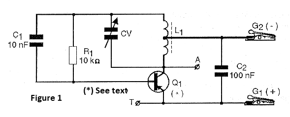
In figure 1 we have the complete diagram of the experimental transmitter.
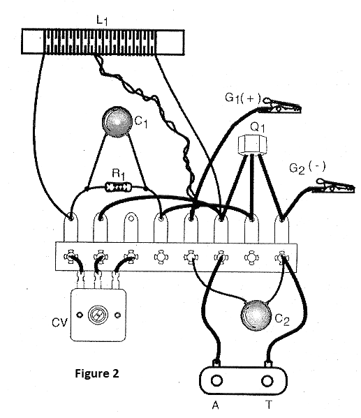
The arrangement of the components on a terminal strip is shown in figure 2.
The coil L1 is formed by 40 + 40 turns of enameled wire 24 or finer in a ferrite rod of up to 20 cm in length and of any diameter. The A and T points are used to connect an antenna and to earth, which gives a small increase in range. The antenna can be a piece of ordinary wire 2 to 5 meters long stretched.
The resistors are 1/8 watt or larger and the capacitors can be ceramic or other. The important thing in this project is that the transistor must be of the PNP type of germanium. Types like 2SB75, 2SB54, OA74 and others that can be obtained from old radios out of use can be experienced. Care must be taken to identify the terminals. Usually in these types the mark corresponds to the collector, the middle terminal is the base and what is left is the emitter.
It is not convenient to use silicon transistors because they need a higher voltage to oscillate and it may not be reached by the experimental cell. The variable capacitor can also be removed from any old medium-wave radio. The transmitter is tuned in.
The cell is made of two metal plugs, one of zinc and the other of copper, approximately 2 x 5 cm which are dipped into a glass with water and salt (dissolve a spoonful of salt in a glass of water). The copper plate will be the positive pole and the zinc plate the negative. Plates should be close but should not touch one another. This battery can provide voltages up to 1 V.
The manipulator can be improvised with a metal plate that makes contact with a screw or a common pressure switch can be used.
WHAT TO EXPLAIN
Look in the physics and chemistry books for explanations of the principle of how batteries work. Then show that the metal plates in the glass with salt and water form an electric heap and that the zinc is consumed as the energy is supplied. Explain that other metal combinations provide different voltages and can be tested and that the liquid (electrolyte) can be any conductive solution.
Also explain that the energy generated by this heap is converted into electromagnetic waves that are irradiated by the small experimental transmitter.
Show that the emitted waves can pass through solid objects like wood, glass, plastic, etc.
USE
Mounted and connected to the transmitter, place a medium-frequency radio in the vicinity of a fre- quency. Then adjust CV to pick up the signal from the device which consists of a sort of "blow" when the manipulator is tightened. Hold the handler tight to make the adjustment.
If you pick more than one signal choose the strongest and check the range. Look for the Morse code on this site to use it in sending a message.
SUGGESTIONS
Try other types of metals and electrolytes. The combination zinc, copper with a solution of sulfuric acid (handle carefully this substance!) Is the one that provides the best results in the stack.
Use a common multimeter to measure the voltage that your experimental stack is providing.
Q1 - Any PNP germanium transistors of general use - see text
L1 - Coil - see text
CV - Variable medium-wave radio capacitor - see text
R1 - 10 k ohm - resistor - brown, black, orange
C1 - 10 nF - ceramic or polyester capacitor - non-critical value
C2 - 100 nF - ceramic or polyester capacitor - non-critical value
G1, G2 - Alligator clips - black and red
Several:
Terminal strip, ferrite rod, experimental pile, wires, solder, etc.


