
In a science fair or as school work this circuit can be used to demonstrate the principle of operation of this device that is used in teaching music and sports activities. Another interesting application for this apparatus is the determination of the speed of walks or marches.
The metronome described is powered by batteries, a battery or a 6 to 12 volt source. The tension chosen will determine the intensity of the cracks produced. The only change in the original design occurs if we want to power the circuit with 12 volt, in which case we should use a TIP32 instead of the BC558 transistor. The assembler, however, should note that this component has a different terminal layout than the original.
The frequency or speed of the beats is set at P1, which covers a huge range of values and can still change if we change C1.
HOW IT WORKS
The circuit basically consists of an oscillator with two complementary transistors where the capacitor C1 together with R2 form the feedback loop. This link applies back to the input of the circuit the signal obtained in the output so that it oscillates. These components together with P1 and R1 determine the frequency of the oscillations.
Since P1 is variable, we can adjust the frequency of the oscillations in this component. The load used on output transistor Q2 is a loudspeaker that reproduces the oscillations in the form of pulses generating audible clicks of good intensity.
ASSEMBLY
In figure 1 we have the complete diagram of the metronome.

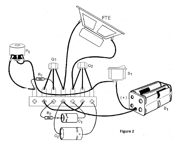
The arrangement of the components on a terminal strip is shown in figure 2.
The resistors are 1/8W or larger with any tolerance and the transistors admit equivalent. Electrolytic capacitors must have working voltages equal to or greater than those indicated in the material list. The potentiometer can be of any type and in reality its value is not critical being able to be between 470 k ohm and 2.2 M ohm.
The speaker will influence the volume. Small 5cm speakers can be used for a portable mount, but for greater sound intensity it is interesting to use a larger speaker mounted on a speaker. For the 12 V version where Q2 must be a TIP32, this component must be fitted with a heat radiator consisting of a U-shaped metal plate.
In the version of 9 V we do not recommend the used of battery but of 6 batteries or source since the consumption is something elevated.
TEST AND USE
To test the device simply place the batteries in the cradle or turn on the external power by observing the polarity and adjust P1 so that the clicks occur at the desired frequency. If it does not reach the desired frequency, change the value of C1.
If the reader wants, he can calibrate the scale of the potentiometer based on a common chronometer or even a real metronome. The scale will be done in number of clicks per second. To use just adjust the unit to produce the clicks at the desired frequency.
If you want a portable mount for hiking, for example, the speaker can be replaced by a low impedance (8 to 32 ohm) headphone and the power supplied by two small batteries.
WHAT TO EXPLAIN
The student should first investigate the purpose of the metronomes in music teaching and if possible even get an old type of rod (a rod that vibrates driven by a spring mechanism). Then explain the operating principle of the electronic oscillator circuits and compare with the old metronomes.
Make an analogy between the length of the rod that determines the frequency in the old types and the value of the capacitor C1 that determines the frequency in the electronic type. In an electronics work, have in hand several capacitor values to use instead of C1 showing how this component influences the frequency of the device.
OTHER APPLICATIONS
Put some Styrofoam balls inside the speaker cone facing up. The polka dots will pop off with every click. Use this experiment to explain how the speakers work.
Semiconductors:
Q1 - BC548 or equivalent - NPN general purpose transistor
Q2 - BC548 or TIP32 - PNP transistor - see text
Resistors: (1/8W, 5%)
R1 - 10 k ohm - brown, black, orange
R2 - 1k ohm - brown, black, red
P1 - 1 M ohm - potentiometer
Capacitors:
C1 - 10 uF / 12V - electrolytic
C2 - 100 uF / 12 V - electrolytic
Several:
FTE - 4/8 ohm - 5 to 10 cm speaker
S1 – On/Off switch
B1 - 6, 9 V - battery or power supply - 12 V - source - see text
Terminal bridge, mounting box, battery holder or power supply, button for potentiometer, etc.


