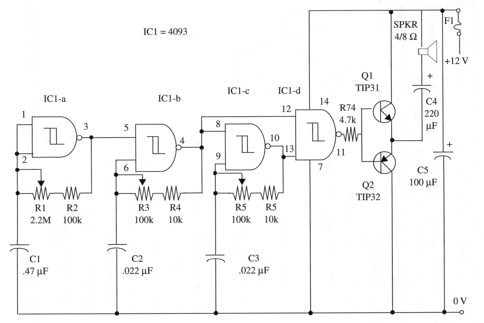
Four gates of a 4093 are used in this circuit that produces a high power tone thanks the high-power transistor in the output stage.
The current drain is up to 1 A, requiring a heavy-duty supply to power the unit.
Output transistors must be mounted on heatsinks, and fuse F1 protects the unit against shorts when used in cars.
A schematic diagram of the Two-Tone Siren is shown in Fig. 1.

You can mount the circuit using a common printed circuit board or a solderless board for experimental purposes.
Pay attention to the position of polarized component such as the transistor and C3.
You can also change the values of C1, C2 and C3 to alter the sounds produced by the circuit.
The circuit can also be powered from 6 or 9 V supplies but with less power for the produced sound.
IC1 - 4093 CMOS integrated circuit
Q1 - TIP31 N PN silicon power transistor
Q2 - TIP32 PNP silicon power transistor
SPKR - 4/8 (2, 4-inch loudspeaker)
F1 - 2-A fuse
R1 - 2,200,000 ohm - potentiometer
R2 - 100,000 ohm, 1/4 W, 5% - resistor
R3, R5 - 100,000 ohm, 1/4 W, 5% resistors
R4, R6 - 10,000 ohm, 1/4 W, 5% resistors
R7 - 4,700 ohm, 1/4 W, 5% - resistor
C1 - 0.47 µF ceramic or metal film capacitor
C2, C3 - 0.022 µF ceramic or metal film capacitors
C4 - 220 µF, 16 WVDC electrolytic capacitor
C5 - 100 µF, 16 WVDC electrolytic capacitor


