Transformerless power supplies are a cheap alternative for those who need low-power direct current without the need to use an expensive and bulky component: the transformer. Of course, the transformer should not be neglected, since it provides the insulation of the network that guarantees the safety of the user of the powered device.
The source we describe does not use transformers and therefore should be used with care, not having to feed any type of equipment that has a connection to your chassis or to a point that can be changed by the operator.
Small home appliances or experimental projects that normally use batteries and that are well insulated in their boxes can be perfectly fed by this source that is characterized by the few components used. Among the devices that can be fed by this source we can mention:
• LEDs
• Small bulbs
• Low consumption electronic circuits
• Sensitive relays
• Low consumption motors
HOW IT WORKS
The basic idea of ??the project is to reduce the voltage of the power network, not by means of a transformer, but by using the capacitive reactance of a polyester capacitor or other type of depolarized.
As the reader must know, the "opposition" that a capacitor presents to the passage of an alternating current depends both on its capacitance and on the frequency of the current. The advantage of using a capacitor as an "opposition" or "resistance" lies in the fact that it does this with a minimum of dissipation of energy in the form of heat, which does not happen with a resistor, as shown in figure 1.

Thus, it is possible to reduce the voltage of the power network to values more appropriate for the work of a source, without using a transformer, with the help of an appropriate capacitor. In our circuit this capacitor is C1 that can have values between 1 uF and 2.2 uF according to the current that we want in the output.
The 470 k ohm resistor in parallel with this resistor is to prevent it from being recharged when the device is turned off which may cause unpleasant shocks.
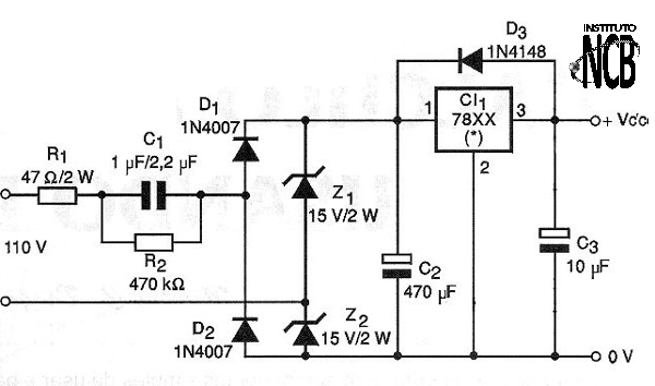
Once the voltage has been lowered by the input network in which the main component is the capacitor we pass the rectification of initial voltage limitation made by means of a bridge. This bridge uses two common diodes and two 15-volt zener diodes that are intended to prevent peaks above 15 volt from appearing in the output regulation circuit, which could cause problems for the integrated circuit.
The capacitor C2 filters the voltage obtained on the bridge in order to obtain a pure continuous voltage. Finally we have the voltage stabilizer circuit whose type will depend on the voltage we want at the output. XX of the type indicated in the diagram indicates the output voltage. So we can use a 7806 if we want 6 V output or a 7812 for an output voltage of 12 volt. For smaller voltages you will need to use a zener of 2 W or greater.
The maximum current of the regulators of the normal series in the TO-220 housing is 1 amp, but in this circuit we will have a lower available current. Even so, it will be interesting to give it a small heat radiator. There are, however, 78XX series regulators with less current capacity (200 mA) that can be used, if the consumption is of that order or less, and which are supplied in TO-54 enclosures (similar to BC548 transistors) and do not require heat sink.
The output of the circuit is decoupled by the capacitor C3 and the diode D2 is intended to protect the integrated circuit when connecting and disconnecting inductive loads.
ASSEMBLY
In figure 2 we have the complete diagram of the source without transformer for the network of 110V. For the 220V network, depending on the current required, capacitor C1 can have its values ??reduced.
We can say that for the same current, in the 220 V network the capacitor can have half the value of the corresponding in the network of 110 V. The arrangement of the components of this assembly on a printed circuit board is shown in Figure 3.
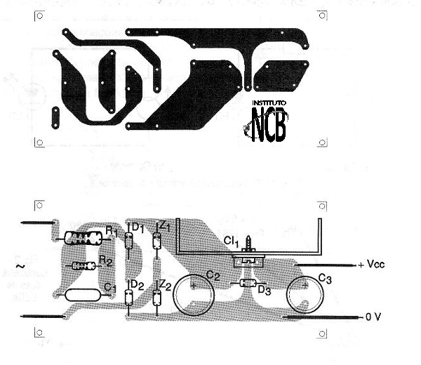
The most critical component of this assembly is the C1 capacitor which must be metallized polyester with a working voltage of at least 200 V if the power supply is 110V. For the network of 220 V the indicated minimum working voltage is 400V. The zener diodes are 2 W or larger and the electrolytic capacitor C1 must have a working voltage of at least 25 Volt.
The capacitor C3 must have a working voltage slightly higher than the source output voltage. The integrated circuit must be selected according to the desired voltage at the output. How to use the power supply depends on the application. Always take into account that there is no insulation of the power network and that no part of the output wires or circuit should be exposed. Contact with these parts would be dangerous.
For powering a project, it can be included in the same board or even made by common wires. To power commercial appliances, use a cable with a suitable connector.
TEST AND USE
To test the unit, connect the power source to the power supply and then carefully measure the output voltage. This should be done by avoiding any contact with live parts, as the power supply is not isolated from the mains and can cause a shock.
Once the operation is verified, only use the power supply, respecting both its current limitation and its polarity. Maximum care should be taken to avoid any contact with living parts. Close the power supply in plastic box to avoid problems.
Semiconductors:
D1, D2 - 1N4004 (1N4007 for the 220 V power grid) or equivalent - silicon diodes
Z1, Z2 - 15V x 2W - zener diodes
CI-1 - 78XX - integrated circuit voltage regulator, according to desired voltage at the output - see text
Resistors:
R1 - 47 ohm x 2W - wire
R2 - 470k ohm x 1 / 2W - yellow, violet, yellow
Capacitors:
C1 - 1 uF or 2.2 uF x 200V (110V network) or 400V (220V network) - polyester - see text
C2 - 470 uF / 25V - electrolytic
C3 - 10 uF / 16V - electrolytic
Several:
F1 - 500 mA Fuse
Printed circuit board, power cable, mounting box, heat radiator for the integrated circuit, fuse holder, wires, solder, etc.