
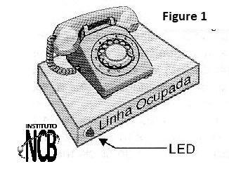
The purpose of this device is to keep a flashing LED near the extension, or the main phone when the other device is being used. This avoids the inconvenience of intercepting someone's conversation while trying to use the phone. The design is very simple, since only a common low-cost integrated circuit is used, as well as few passive components that can be easily obtained.
HOW IT WORKS
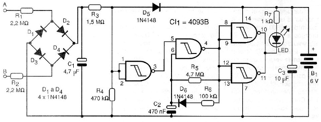
The bridge of diodes and resistors from R1 to R3 in addition to capacitor C1, maintains the input of a reversing port of the 4093 polarized high when the phone is off the hook. Thus, the oscillator formed by the second port of 4093, and whose frequency is determined by C2 and associated resistors, remains disabled.
When the phone is taken off the hook and the line voltage drops, the voltage at the inverter port input drops, and with that its output goes to high level, which enables the oscillator. The oscillator controls a power stage that excites one LED and makes use of the other two ports of the same integrated circuit.
When the oscillator is disabled, the output of the power circuit remains at the low level, and thus the indicator light stays off. With the oscillator in operation, the power output oscillates between the high level and the low level, which causes the LED to keep flashing, alerting you to the use of the extension.
The diode D6 in the oscillator aims to obtain a short active cycle for the oscillator so that we have short blinks, and with this less energy expenditure of the batteries.
The relationship between R5 and R6 determines this active cycle and can be altered according to the wishes of the designer. Lower value of R6 means shorter blinks and lower consumption.
Generally, the drained current in the standby condition is less than 0.5 mA and this current rises to 5 mA during the blinks. However, a set of 4 small batteries that power the circuit should last for many months, so there is no need for a general switch to the device since it must remain constantly on.
ASSEMBLY
In figure 2 we have the complete diagram of the line indicator.
The arrangement of the components on a printed circuit board is seen in Figure 3.
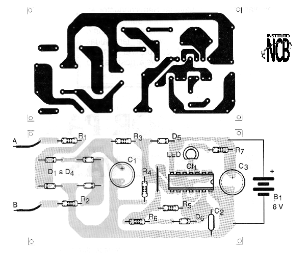
For the integrated circuit, a 14-pin DIL socket can be used for safety and ease. The LED is red in color and should be on the plastic box panel where the assembly will be installed. The dimensions of this canister are basically determined by the size of the battery holder because the plate is quite small.
The resistors are 1/8 W and the electrolytic capacitors must have a working voltage of 12 V or more. The diodes support equivalents such as 1N914. For connection to the telephone network, a pair of screw terminals may be used, from which wires must come out which will parallel the telephone line in its connector.
TEST AND USE
Just connect the unit to the telephone line and put the batteries in the holder. When the handset is off the hook, the LED should flash. If desired, change the values of R5 and R6 to change the frequency and active cycle of LED blinks.
To use just note that when the LED is flashing someone will be using the extension or the main phone.
Semiconductors:
CI1 - 4093B - CMOS integrated circuit
D1 to D6 - 1N4148 - general purpose diodes
LED - common red LED
Resistors: (1 / 8W, 5%)
R1, R2 - 2.2 M ohm
R3 - 1.5 M ohm
R4 - 470 k ohm
R5 - 4.7 M ohm
R6 - 100 k ohm
R7 - 1 k ohm
Capacitors:
C1 - 4.7 ?F / 12 V - electrolytic
C2-470 nF - ceramic or polyester
C3 - 10 ?F / 12 V - electrolytic
Several:
B1 - 6 V - 4 small batteries
Printed circuit board, mounting box, battery holder, integrated circuit socket, wires, solder, etc.


