
The alarm displayed detects when the sensor, a pendulum contact switch is activated, even for fraction of a second. The produced pulse triggers the circuit that closes the contacts of a relay and keeps it activated for a time that can be programmed between a few seconds up to about 15 minutes. In our prototype, mounted in contact array, the drive is an LED, but instead a horn or other warning device can be connected.
In the standby condition the consumption of the appliance is less than 1 mA and in the trip condition the consumption is higher, depending only on the relay used.
The Circuit
This circuit consists of a direct application of the 555 in the monostable configuration. When its trigger input (pin 2) is grounded instantaneously, the output of 555 goes to high level remaining in that state for a time that depends on R and C.
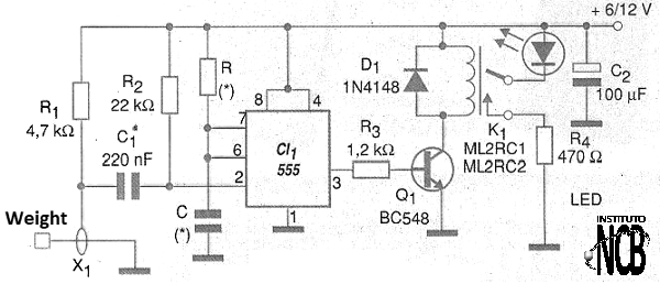
The R values may typically be between 1 k and 1 M, whereas the C values may be between 100 nF and 1000 uF typically. The drive time can be calculated by the formula:
t = 1.1 x R x C
At where:
t will be obtained in second
R must be given in ohm
C should be given in farads
For 100 k and 1 uF, for example, we obtain approximately 110 seconds, which taking into account the tolerances of the components results in approximately 2 minutes.
The signal at the high level obtained at the output of 555 serves to saturate a transistor that has as load collector the relay. We recommend the use of a sensitive relay with a maximum current of 50 mA.
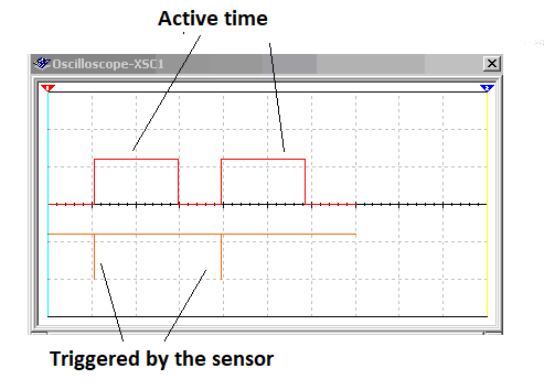
The circuit can be powered with voltages of 6 V or 12 V depending on the relay used or the power supply. In figure 2 we have the waveforms obtained in a simulation of this circuit with the Multisim (National Instruments Simulation and Projects Program).
Assembly
The circuit may be mounted on a common, universal printed circuit board or even in a contact array. In our case, we assemble this circuit into a protoboard, obtaining the placement of components shown in figure 3.
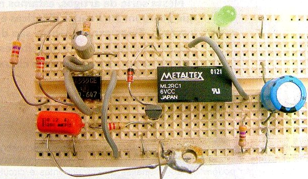
Note that a Metaltex DIL relay was used that fits perfectly in the contact array and is therefore the ideal component for the development of this type of design.
The sensor can be made with bare wires and a small weight, as shown in figure 4.
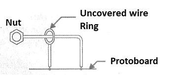
Note that the ring does not lean against the sensor wire, which will only occur when it is subjected to some kind of swing. To test the circuit, simply connect a load to the contacts of the relay as shown in figure 5 and then turn it on. When the sensor is balanced so that the contact occurs, the relay must trip with the load drive for the time determined by R and C.
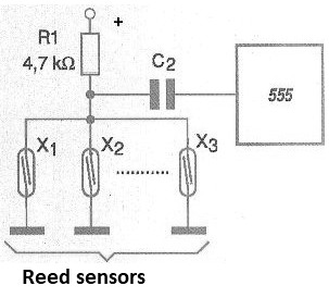
The same circuit can also be used with reed-switches, several of them connected in parallel, as shown in figure 5, protecting a wider domestic or commercial installation. Sensor wiring can be long and in this case the use of a source or battery is recommended to allow the system to also power a higher power warning system.
CI-1 - 555 - integrated circuit
Q1 - BC548 - NPN general purpose transistor
D1 - 1N4148 - general purpose diode
K1 - 6 or 12 V relay - depending on power supply
X1 - Pendulum sensor - see text
R1 - 4.7 k ohm x 1/8 W - resistor - yellow, violet, red
R2 - 22k ohm x 1/8 W - resistor - red, red, orange
R - resistor - see text
R3 - 1.2 k ohm x 1/8 W - resistor - brown, red, red
C1 - 220 nF - ceramic or polyester capacitor
C2 - 100 uF - electrolytic capacitor
C - electrolytic capacitor - see text
Several:
Printed circuit board or array of contacts, power supply or batteries, wires, solder, etc.


