Obs. This project after be published in a Brazilian Magazine was included in my book CMOS Projects and Experiments (Newnes 1999)
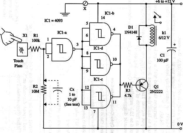
The circuit replaces the relay with a Darlington power transistor, and it can be powered from 6 to 12 V supplies. Current drain depends on the controlled load.
A schematic diagram of the Touch Switch is shown in Fig. 1.

The transistor must be mounted on a heatsink. Note that this is a non-latching circuit. The loads are on only during the time you are touching the sensor plates.
You can also replace the bipolar transistor with a power FET to increase power capabilities of the circuit. Proper positioning of the load must be observed if it is a motor or other polarized device.
IC1 - 4093 CMOS integrated circuit
R1 - 100,000 ohm, 1/4 W, 5%
R2 - 4,700,000 ohm, 1/4 W, 5%
R3 - 4,700 ohm, 1/4 W, 5%
Q1 - TIP115 N PN Darlington power transistor
D1 - 1N4148 general purpose silicon diode
X1 - Touch sensor (see text)
R1 - 4,700,000 ohm to 10,000,000 ohm, 1/4 W, 5% resistor (see text)
R2 - 4,700 ohm, 1/4 W, 5% resistor
C1 - 100 µF, 16 WVDC electrolytic capacitor


