A miniature "fire escape" produced by sparks that can easily exceed 20 000 volts. This is the assembly that we describe using a SIDAC as the basic component. In figure 1 we give an idea of the effect obtained.
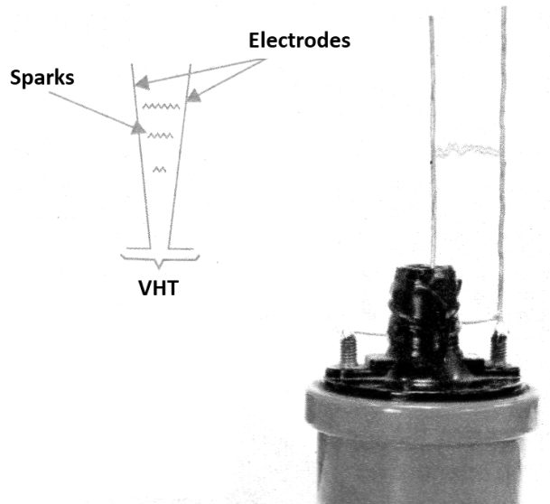
The reader can use it to make demonstrations with high tension, in fairs, classes, and even for decoration. In physics classes, sparks serve to show some properties of high voltages such as dielectric strength, the thermal effect and also allows the measurement of voltages to be performed based on the size of the spark.
The SIDAC
Sidac stands for Silicon Diode for Alternating Current. It is a relatively new component that has very interesting negative resistance properties. The appearance and symbol of this component are shown in figure 2.
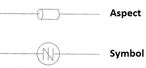
When the voltage between the terminals reaches a certain value, which in the type we use in this project is 240 V, it goes from the non-conduction state to full driving. In this state it can conduct chains of several amps, without problems.
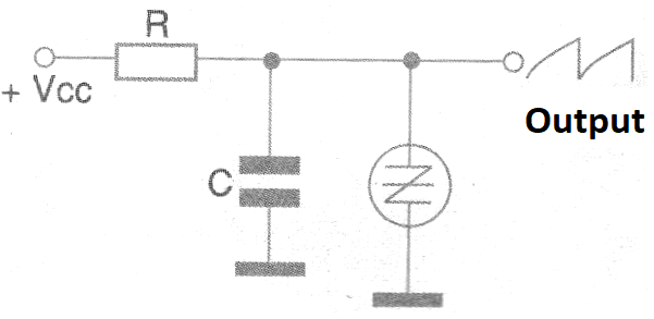
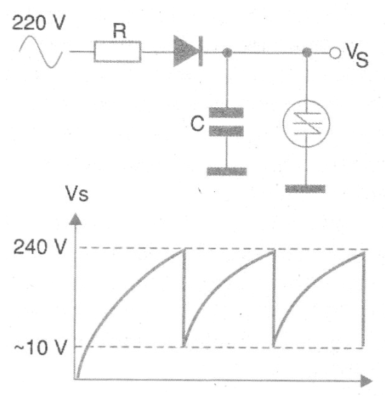
In other words, it is a negative resistance device, similar to the neon lamp, that can be used in a relaxation oscillator with the configuration shown in figure 3.
The SIDACs can then be used in circuits that produce high voltage pulses of great intensity, fed directly by the power network of 110 V or 220 V, depending on the type. In our project, since we are using a 240 V SIDAC, the circuit must be powered by the 220 V network. If the reader is to power the circuit in the 110 V network, simply use a 110 VAC SIDAC.
How it works
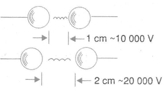
To generate a high voltage that produces sparks between two wires a voltage of 10,000 volt is needed for each centimeter they are separated. Thus, if the wires are at a distance of 2 cm we will need at least 20 000 volt for a spark to jump between them, as shown in figure 4.
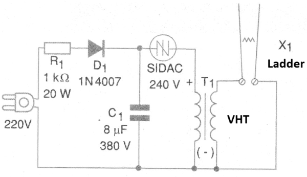
The idea of the project is to generate this high voltage using a car ignition coil and a relaxation oscillator with a SIDAC. Common ignition coils can generate voltages up to 40 000 volt! In the circuit, the input resistor R1 serves as a current limiter, which is rectified, thereby serving to charge the high voltage capacitor C1.
Since in the 220 V grid we have peaks that reach more than 330 V, we have no problem getting a 240 V load that the SIDAC needs to fire. However, it is necessary that the capacitor is of a special type capable of withstanding this voltage. We then use a depolarized 8 uF capacitor with a working voltage of at least 350 V, for greater safety. The charge of this capacitor will determine the intensity of the pulse produced.
Thus, together with the resistor R1, the capacitor and the SIDAC form a relaxation oscillator that produces pulses with 240 V of amplitude, as shown in figure 5.
These pulses are applied directly to the primary winding of an ignition coil, thus producing high voltage pulses of great intensity. The high voltage pulses are applied to the electrodes that must produce the sparks.
Attention! Watch out! Danger!
In addition to operating directly connected to the power grid, the circuit generates dangerous voltages! Keep it away from people, and do not touch any part of it when in use.
If possible, close it in a glass or plastic vial to make the demonstrations.
Assembly
In Figure 6 we have the complete diagram of the Jacob Ladder.
As it is a circuit that uses few components and some of them until quite bulky like the power resistor and the capacitor, the assembly can be carried out based on a terminal strip. The assembly may then be secured to a plastic or wood base as shown in Figure 7.
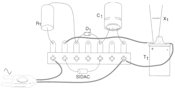
In the assembly a 240 V SIDAC of the ON-Semiconductor was used but equivalent for the same voltage serve. The capacitor must be of the depolarized type to 350 V or more with capacitance between 4 and 8 uF. Do not use electrolytic capacitors.
The rectifier diode is 1N4007 and the ignition coil can be of any type for automobile. There is no need for a fuse at the input because the resistor limits the current and if something happens the resistor itself acts as a fuse (fusistor).
The ladder itself (X1) is manufactured from two pieces of 15 to 20 cm of bare yarn 16 or 18 placed parallel to each other by a distance of 1.5 to 2.5 cm. The ideal distance should be obtained experimentally depending on the performance of the circuit.
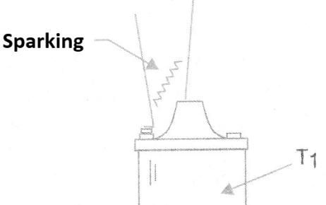
A critical point is the separation of the wires at the base which should be such as to avoid sparking at that point, as shown in Figure 8.
Test and Use
To prove, simply connect the circuit to the power grid. Do not touch any part of it when it is switched on. Noise from high voltage production should be heard and sparks should already jump between the wires of the ladder.
If noise occurs, but sparks do not appear, turn off the power and pull the wires until sparks occur. If the sparks obtained are very small this may be due to the type of coil used that should be replaced. Some old car coils generate lower voltages than those used in modern cars.
Once the operation is confirmed, it is only to make the installation final. The approximate consumption of the appliance in the 220 V mains is 50 W. The heating of the resistor during operation is normal.
Try to Explain:
a) Because the sparks go up when they are produced
b) Because the sparks are not exactly straight
Try to Do (very carefully!)
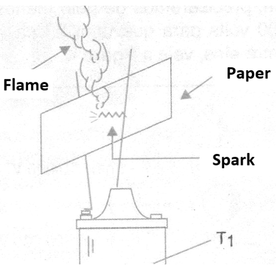
a) Put a strip of paper between the sparks. The sparks, after a certain time, will burn the paper, and will ignite it, as shown in figure 9.
b) Approach the staircase with a fluorescent lamp. It should be lit by the presence of the high voltage field.
SIDAC - SIDAC 240 V
D1 - 1N4007 or equivalent - silicon diode
C1 - 8 uF x 350 V or more - depolarized capacitor (AC type)
R1 - 1 k ohm x 20 W - wire resistor
T1 - Car ignition coil - see text
X1 - Electrodes - see text
Several:
Mounting base, power cable, terminal bridge, wires, solder, etc.