Induction signal transmission systems are used in spying because they eliminate the need for a wire between the location of the microphone and the location where the spy with the earpiece. In this way, uncovered the microphone, it is difficult to find the location in which the spy may be.
Our experience shows how this inductive ring listening or transmission system can be implemented in a simple way for demonstrations or even for a remote sound equipment system. The basic idea is to apply the output of an amplifier to a large coil, so that it produces a strong magnetic field that can be picked up at a good distance. For a powerful amplifier, and a sensitive pickup system, this distance can exceed 3 meters.
For our case, as the system is quite simple we will have a smaller range, but because walls are much thinner than this, the signal can cross them easily. We can stream music through the wall or even design a wireless communications system with a pair of receivers and transmitters.
How it works
The principle of operation is easy to understand: by applying the output signal of an amplifier to a coil made with some coils of common wire, we have the creation of a strong magnetic field with the same characteristics of the current that would circulate in a loudspeaker.
Since this current corresponds to amplified sounds, the field carries this information and can traverse objects such as walls and floors. To pick up the signal, all we need is a second coil with many coils of fine enamelled wire.
The magnetic field created by the transmitter coil when cutting the turns of the receiving coil induces currents with the same characteristics of the original sound. We then have two possibilities to recover the original sound: we can connect this coil to a simple headset (which must be of a sensitive type of crystal or piezoelectric) or an amplifier input.
Assembly
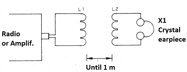
In figure 1 we have the complete diagram of the system with crystal earphone.

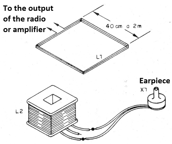
In figure 2 we show the appearance of the assembly.

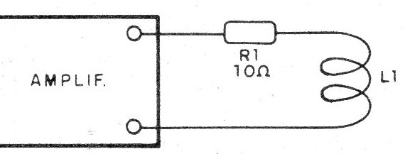
The coil L1 is formed by 5 to 10 turns of common wire with a diameter that can vary between 40 cm of 2 m. This coil is connected to the output of the amplifier, which if it has more than 1 W should have a resistor of 10 ohm x 10 W connected in series, as shown in figure 3.

The receiving coil is a common power transformer or output from old tubed apparatus from which the number has been withdrawn. In the case of the power transformer, we connect the handset to the primary winding. It is very important that the phone is high impedance because other types of handset will not work.
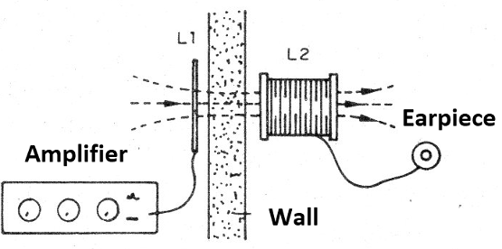
In figure 4 we show how to use the system in a communication through a wall.

L1 - 5 to 10 turns of common thread - see text
L2 - transformer winding - see text
X1 - Crystal earphone
R1 - 10 ohm resistor x 10 W
Several:
Wires, solder, box for mounting the receiver, etc.


