
A voltage-controlled oscillator using TTL components may be required in some type of project. If the reader already needed this type of circuit he still needs it, we describe in this article a configuration that can be very useful. The idea that can be very useful for our readers caught our attention in order to remove the basic configuration that we now bring to our readers, of course, citing the source.
Applications for voltage controlled TTL oscillators can be applied.
* Voltage measurement using a TTL frequency meter.
* Conversation of analog quantities such as resistances, temperatures or light intensities for processing through TTL circuits.
* Electronic musical instruments.
The oscillator can use both standard TTL integrated circuits (standard) and the S and LS series. Those of the standard series, however, will have a maximum frequency much lower than 50 MHz, reaching only 15 MHz.
HOW IT WORKS
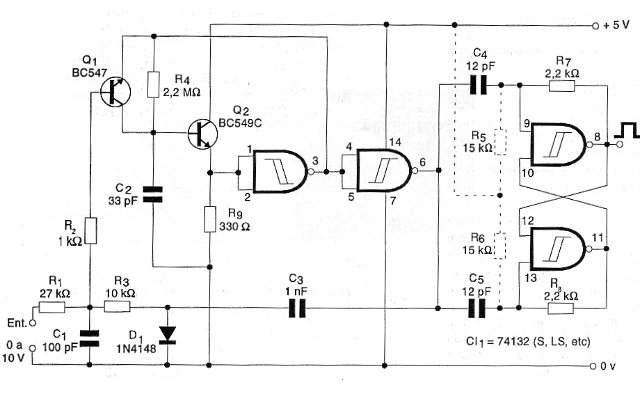
The circuit is based on an oscillator with Schmitt NAND gates that are connected as inverters. The transistor Q2 is connected as an emitter follower at the input of the main port in order to increase the resistance of the input and the communication to allow the use of maximum value feedback resistors. In any case, the resistor may have a value as high as 2.2 M ohm (R4).
The Q1 transistor works as a frequency control stage, functioning as a variable feedback resistor in parallel with R4. Thus, when Q1 leads, decreasing a feedback resistance, the frequency of the oscillator which is limited by R4 and also by C3 increases.
The control of this frequency is then done by a voltage applied to the base of this transistor via R1 and R2.
The duration of the pulses produced by the oscillator basically depends on the time of signal propagation through the trigger doors. For standard types this time is in the order of 30 ns as well as the LS series. However for the S series this time is 15 ns.
To obtain a signal with a 50% active cycle, a flip-flop is used with two other ports of the same integrated, in order to function as a divider by 2.
Thus, for a 30 MHz signal generated without an oscillator, we have a 15 MHz output in this step. If the reader is not concerned with the fact that the circuit generates rectangular signals and can work with pulses in its application, an output can be obtained on pin 6 of the integrated circuit, which is a second port after the oscillator.
The diode and C3 provide a control feedback in order to obtain a more stable operation for an input stage.
The resistance R1 determines a range of control voltages and the value given for a range of 0 to 10 volts. Changes can be made depending on the application.
It is important to observe the curve of the circuit's response in the linear or to want that it does not have the frequency control exactly in direct correspondence with an input voltage.
ASSEMBLY
In figure 1 we have the complete diagram of the oscillator.
This is the type of circuit that cannot be used in other cases, but it is part of the most detailed project. However, if the readers want to mount it on a plate, in figure 2 we have a suggestion for the arrangement of components for this purpose.
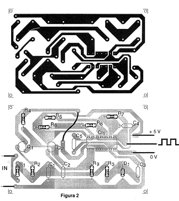
The resistors are all 1/8 W or larger and the capacitors must be ceramic of good quality. As connections between the components must be very short, especially at the highest frequencies, and eventually capacitors of 10 nF must be connected between the supply pins of the integrated in order to avoid instabilities.
Instabilities can also occur with integrated LS at the higher frequencies requiring the placement of resistors R5 and R6 in the circuit.
The transistors must be indicated, mainly Q2, which must be of the C series, as a high gain is needed at this point in the circuit.The diode admits equivalents.
TEST AND USE
To prove it, we can use a variable source at the input or even a potentiometer as a voltage divider. At the output we connect a frequency meter.
Depending on the application, it may be interesting to draw the circuit response curve. Changes in C2 can be made depending on the desired operating frequency.
At higher frequencies it may be necessary to decrease C4 and C5 to obtain more stability and at very low frequencies these capacitors may need an increase in value.
Semiconductors:
CI-1 - 74132 (L, LS, S, etc.) - TTL integrated circuit
Q1 - BC547 - general purpose NPN transistor
Q2 - BC549C - high gain NPN transistor
D1 - 1N4148 – general-purpose diode
Resistors: (1 / 8W, 5%)
R1 - 27 k ohm
R2 - 1k ohm
R3 - 10k ohm
R4 - 2.2 M ohm
R5, R6 - 15k ohm
R7, R8 - 2.2 k ohm
R9 - 330 ohm
Capacitors:
C1 - 100 pF - ceramic
C2 - 33 pF - ceramic
C3 - 1 nF - ceramic
C4, C5 - 15 p F – ceramic
Several:
Printed circuit board, socket for the integrated circuit, wires, solder, etc.


