

The 555 integrated consists of a "timer" normally found in an 8-pin DIL housing, as shown in Figure 1.
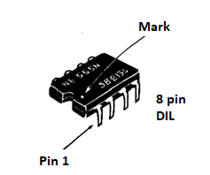
It does not matter to us to say here what is inside this enclosure, that is, the equivalent configuration of this integrated, but rather how it can operate and the function of its pins.
The 555 can typically operate in two forms:
a) Astable Operation
In this mode, the 555 oscillates at a frequency that depends on the external components, in this case the resistors R1, R2 and the capacitor Cl of the circuit in Figure 2.
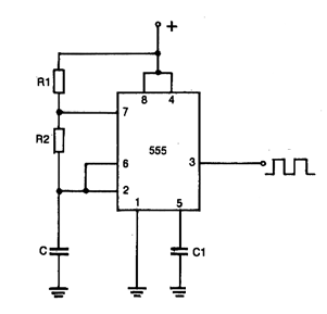
The formula for calculating the frequency of operation based on these components is:
f = 1.44 / [ (R1 + 2R2) * C ]
Where R1 and R2 are given in ohms, C in Farads and f in hertz.
In practice, there are limit values for all three components. Thus, R1 and R2 combined must not exceed 3 megohms, while the minimum value of R1 or R2 cannot be less than 1 k ohm.
For C we have a minimum value in the order of 500 pF and a maximum that is determined by the quality of this component, since only the leaks can compromise the functioning of the circuit. The supply voltage of the 555 can be between 4 and 15 V and at its output we can connect loads which drain up to 200 mA to earth.
The signal obtained at the output of integrated 555 is rectangular. The duration of each cycle is given by R1 and R2, while the interval between pulses is given by R2.
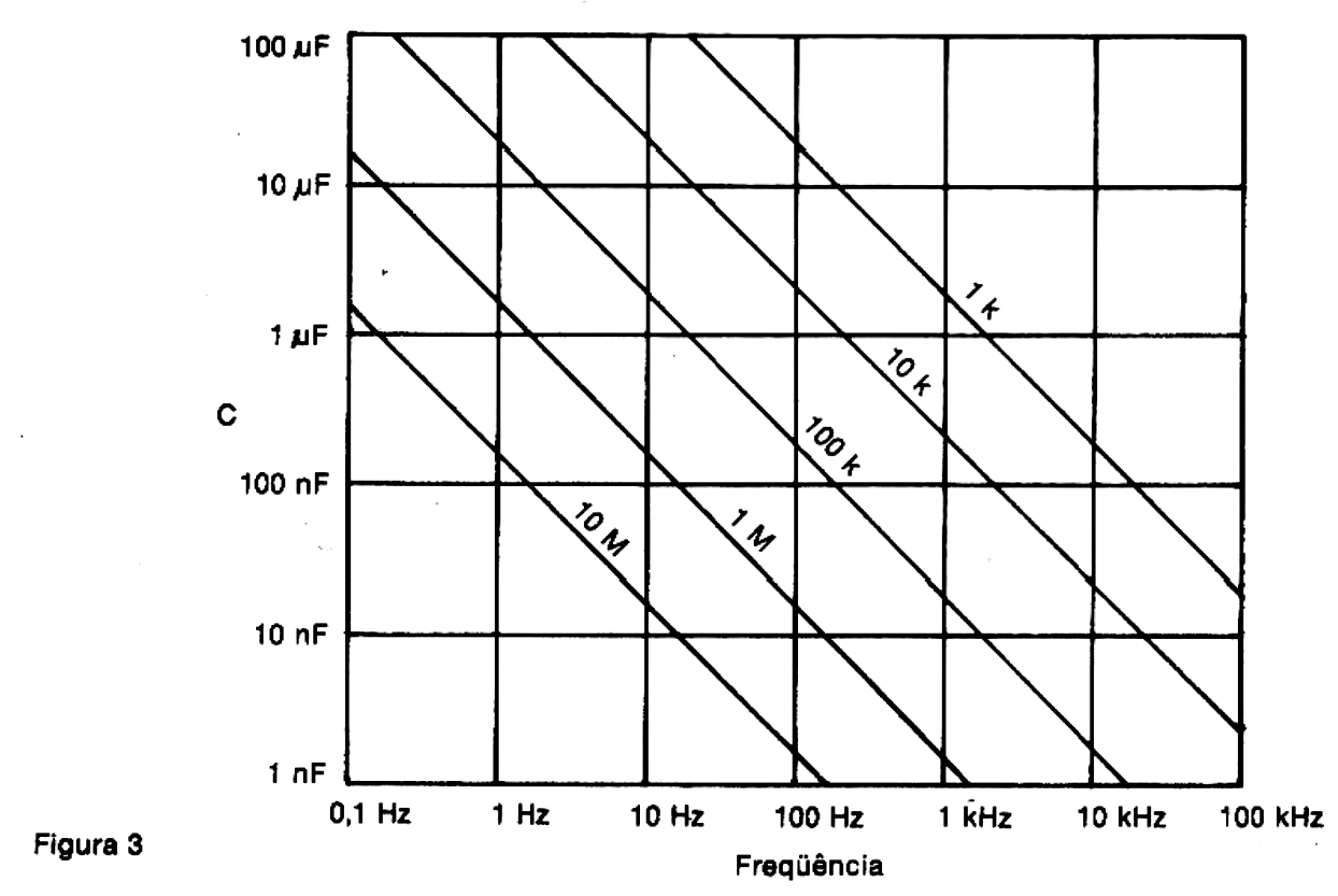
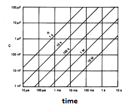
In Figure 3, we show a graph in which we can determine the values ??of the different components for operation at a given frequency.
At pin 5 of the integrated, we can connect a decoupling capacitor which avoids operating instabilities. This capacitor is typically ceramic, 100 nF.
Powering the 555 with a voltage of 5 V, it becomes compatible with the integrated TTL family.
The frequency limit for this integrated circuit is around 1 MHz, but operation at this point is not recommended. Typically, the practical limit for an operation with maximum performance is around 300 kHz.
b) Monostable Operation
In the monostable operation, a pulse applied to pin 2 of the integrated unit causes it to have an output voltage at the output pin 3. This voltage remains at this output for a period which does not depend on the duration of the excitation pulse. This period depends only on the values ??of the components R and C of the circuit of Figure 4.
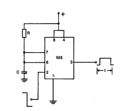
We can calculate this time by the formula:
T = 1.1*R*C
where R is given in ohms and C in farads, the time being obtained in seconds.
In this case too, there are limits to the components used. Thus, the maximum value of R is around 3.3 M ohms and the minimum around 1 k ohm. The minimum recommended C value is 500 pF and the maximum value depends only on the quality of the component, which must not leak.
In this case, we can also give a graphic to determine the component values (Figure 5).
The characteristics of output and supply voltage are the same as those obtained in the astable operation.
Given this, we can move on to some practical circuits:
1. Audio Oscillator I
A simple audio oscillator can be obtained from the circuit in Figure 6.

At this circuit, we use a potentiometer to control the frequency (P1) and a selector switch to change capacitors, and, therefore, the selection of ranges.
At the output there is a second potentiometer which controls the signal strength applied to the external circuit. Note that the resistance of this potentiometer, and therefore of the load, is limited to a minimum of 100 ohms.
A capacitor isolates the circuit, thus allowing the application of the signal in amplifiers, intercoms, medium and high impedance transducers, etc.
The power can be done with voltages of 6 to 12 V, normally.
2. Audio Oscillator II
In this oscillator, the signal obtained is much stronger, and can be applied to a loudspeaker or similar device, such as a low impedance phone (Figure 7).
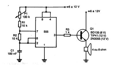
With a supply of 6 V we obtain a power of approximately 1 W and with a supply of 12 V this power approaches 4 W, so it is necessary to mount the transistor in a good heat radiator.
The tone is continuous, and its frequency is adjusted at the pot. For a different range of frequencies, just change the capacitor. The graphic given for the astable operation allows to determine exactly the value of this component for the desired frequency.
For a power of up to 6 V, medium power transistors with collector currents (IC) typically between 1 and 3 A, such as BD135, BD137, BD139, TIP29, TIP32, etc., can be used.
For a 12 V power, transistors with currents from 6 A, such as TIP41, 2N3055, etc., must be used.
The speaker must be 4 or 8 ohms, capable of withstanding a power of at least 10 watts.
We note that the tone produced by this oscillating circuit is continuous and is therefore indicated more as an alarm or horn. This is not a siren effect circuit.
The siren effect can be achieved by the following circuits.
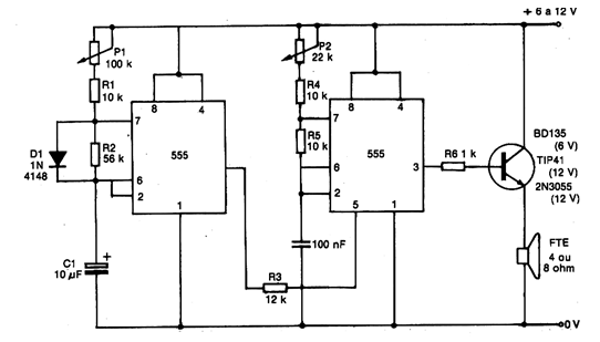
3. Siren I
The indicated circuit is an intermittent one in which we use two 555 integrated ones, one as a low frequency oscillator (audio) and the other as a modulator (Figure 8).

As we can see, the first integrated 555 (CI-1) operates at a very low frequency, given by the capacitor Cl and adjusted at the potentiometer P1.
This oscillator modulates, that is, it interrupts the signal produced by the second integrated at regular intervals, as the application at the pin 4.
When the pin 4 is at the high level, the second oscillator is released (CI-2), then producing the tone that is set at the potentiometer P2.
The power obtained at the output of the 555 is good, but it does not work to drive a speaker, regarding its impedance. Thus, in this circuit, as in the previous one, we use a transistor as a driver for a speaker.
Depending on the characteristics of the source (supply voltage), we have several options of transistors which can be used, exactly as in the previous circuit.
Remember that the capacitor C3 can be changed, according to the desired tone for the audio signal.
Connecting this siren to a higher power amplifier is very simple. In this case, it is enough to eliminate the stage with the transistor, connect the 1 k ohm resistor to the ground directly (to work as load) and make the connection to the amplifier input through a 100 nF ceramic capacitor.
We also remember that the source for this circuit, as for the previous one, must have current capacity according to the power. For the 6 V version, it is necessary to use medium or large batteries and, for the 12 V version, a car battery or power supply with at least 2 A.
4. Siren II
This circuit, when properly adjusted, imitates the siren of the English police, with sounds suddenly changing in tone, in a very interesting effect (Figure 9).
As we can see, the two 555 are connected to the configuration of the astables, the first being adjusted to a low frequency, producing the modulation.
The capacitor C1, 10 µF, is responsible for the modulation that is adjusted at the potentiometer Pl. The value of this potentiometer can vary between 100 k ohms and 220 k ohms without problems. The higher its value, the slower the modulation that can be achieved.
The output signal of the first integrated modulates the second via the decoupling pin 5. A resistor, whose value can be changed experimentally in the range of 8k2 to 15 k ohms, determines the frequency modulation of the second oscillator.
The frequency of the second oscillator is adjusted at the potentiometer of 22 k ohms and its average value is given by the ceramic capacitor of 100 nF.
The output of this circuit, made on pin 3, is also of high impedance, and a transistor must be used as a driver to directly excite a speaker.
The transistor will depend on the supply voltage, as we have seen in the previous circuits.
There is also the possibility of using an external amplifier, whose connection will be made as in the previous circuit.
5. Monostable Relay (Alarm)
This circuit can be used as an efficient burglar alarm by simply choosing the sensor used (Figure 10).
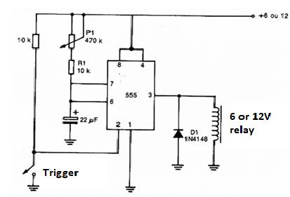
The behavior of the circuit can be analyzed as follows: when the input of the monostable (pin 2) is momentarily grounded by the switch used as a sensor, the output of the integrated (pin 3) is brought to the level Hl, which corresponds to the presence of a voltage in the same order as the supply voltage; this voltage is insufficient to activate the relay, which can then supply a powerful alarm circuit.
The activation period will be given by the setting of P1 and the value of C1, which can be between a few seconds and even more than half an hour.
The relay contacts withstand high currents, but their limits must be respected. We observed that the trigger can be done with low current switches, such as "reed switches" or "micro switches".
Conclusion
Of course, in one article, we don't have enough space to explore all the 555's possibilities. In addition to conventional circuits, the C-MOS equivalent of this integrated, the 7555, already exists on the market, which allows you to obtain longer periods of time, lower frequencies and less consumption, which opens up a multitude of applications for the designer.


