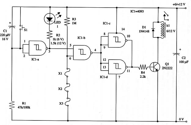
Loads up to hundreds of watts can be controlled with this version of the Delayed Turn-On Alarm. This circuit drives a relay that controls heavy-duty loads such as sirens, horns, and small appliances powered from batteries or the ac power line.
Operation is the same as described in the previous project, and a turn-on delay of about 20 seconds is obtained with the components shown in the schematic diagram. You can alter the time delay by changing both C1 and R1. Cl should be between 10 and 1,000 µF, and R1 between 10 k ohm and 1 M ohm.
The sensors are magnetic types or wires, normally closed, and several of them can be wired in series to protect large areas, as explained in the first version (ART002E).
Power comes from AA cells, a battery, or ac-to-dc converters rated to currents of 250 mA or more. As the current drain is very low when the relay is off, batteries can be used.
A schematic diagram is shown in Fig. 1.

K1 depends on the power supply voltage and current drained by the load. A mini DPDT, 1 A relay (Radio Shack 27 5-249) can control loads up to 100 W from the ac power line. This relay uses a 12 V power supply in this project.
If you want to control heavy-duty loads, you can replace this relay with a 10 A mini SPST relay (Radio Shack 275-248), but you have to note the difference in the terminal layout.
To operate the unit, press S1 before leaving home. After the programmed time delay, the alarm will turn on automatically.
IC1 - 4093 CMOS integrated circuit
Q1 - 2N2222 N PN general purpose silicon transistor
D1 - 1N4148 general purpose silicon diode
LED1 - Red common LED
K1 - 6 V or 12 V relay (see text), 1 A DPDT mini relay, Radio Shack 27 5-249
or equivalent
S1 - SPST momentary switch
R1 - 47,000 ohm or 100,000 ohm, 1/4 W, 5% resistor (see text)
R2 - 1,000 ohm (6 V) or 1,500 ohm (12 V), 1/4 W, 5% resistor (see text)
R3 - 1,000,000 ohm, 1/4 W, 5% resistor
R4 - 2,200 ohm, 1/4 W, 5% resistor
C1 - 220 µF, 16 WVDC electrolytic capacitor
C2 -100 µF, 16 WVDC electrolytic capacitor
X1, X2, X3 - Normally closed sensors (see text)


