There are several techniques for isolating a shield from a microcontroller. We can do this through transformers if the signals to be transferred are pulses or an alternating current. We can also use capacitors in these cases, although safety is limited in insulation to the working voltage of the capacitors, and we can also use optical couplers. In fact, the most widely used solution nowadays is the one that makes use of optical couplers obtained in the form of integrated or optocouplers, which consists of having a LED that emits the control signal to the receiver, both in an input and output shield. In this article we will give some immediate practical circuits that can be used in shields for common microcontrollers such as Arduinos, PICs, MSP430, and many others.
With the direct use or adaptation of these shields IoT designs, wearable, automation, security, robotics and much more can be developed easily.
Many of these circuits can be accessed in an individual way in our Circuit Bank section. The advantage of this article is that they are organized in one place.
Initial considerations
The microcontrollers have 3.3V and 5 V inputs and outputs which should be used to power the shields in some cases or separated driver LEDs or the optocouplers.
This implies in the case of LEDs using resistors in series whose values ??can be between 100 and 220 ohm for the outputs of 3.3 V and from 330 ohm to 470 ohm for the outputs of 5 V.
One must always take into account the maximum current that the output of the microcontroller can provide in these cases when the insulated shield is of output.
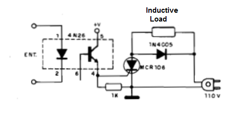
1. Opto-isolator in the SCR control (power control)
With the circuit below it is possible to control a SCR like the MCR106 or another of the series like the TIC106 from a signal applied to the 4N26 (optical coupler). Excellent insulation is obtained and the circuit can control high current loads. The insulator transistor must be fed with continuous voltages from 6 to 12 V which should come from a separate source of the microcontroller, to maintain the insulation. The circuit also works with 220 V using an appropriate SCR. To use as a shield, use in series with the coupler LED resistor from 100 to 220 ohm for 3.3 V outputs or 330 ohm for 5 V outputs. Modify the sensitivity to the 1 k resistor.
2. Optocoupler with a Trigger
The circuit has a trigger that acts on a relay switching it with high speed without repiques. In the original from an old publication it was used a lamp at 400 mA but as a shield it is recommended to use a LED like in the previous circuit. The circuit triggers a 100 ohm relay for a 9 V voltage. Other relays can be used. The circuit has its trigger action given by the 10 ohm resistor which feeds back the signal from the transistors. Equivalent switching transistors such as the 2N2222 can be used in this application.
3. Optocoupler for 10 mm
This circuit is used in an optical shield or coupler where the distance between the emitter and the phototransistor can reach 10 mm with the original lamp from the old design. The circuit can be powered by voltages of 9 V and the used relay is of 100 mA. Equivalent transistors such as BC548 can be used. The lamp can be replaced by an equivalent power LED or even with optical features (lens). The circuit is suggested by Texas Instruments in its Optoelectronics Manual. Instead of the lamp we suggest a white LED with a resistor from 47 Ω to 220 Ω in series, controlled by the output of the microcontroller, obtaining the desired isolation.
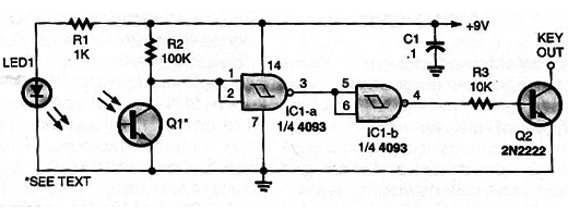
4. Optical Shield with the 4093
The sensor is an optical coupler with a LED and a phototransistor. In a shield the LED is driven by the microcontroller and not as it is in the original circuit with the same source. The circuit is activated when the light is interrupted. At the output (pin 10) it already has the power stage for the activation of higher current loads, like a relay, motor or solenoid. The wire to the sensor should be short. The circuit should not be powered by a transformerless source. The LED can be driven by a microcontroller, in which case the circuit works as a shield.
5. Optical Shield with Transistors
The light interruption from the lamp or LED which reflects on the phototransistor triggers the relay. The circuit has a short radius of action (a few centimeters) serving in either optical controls or optical switch. A possible application is in a limit stop switch or in a position detector of a mechanical part. The circuit is powered by 9 V, using a 6 V relay since the 10 ohm resistor provides a voltage drop for this component. The transistors can be replaced with equivalents like the BC548 and for the phototransistor we can also use an equivalent. This circuit is suggested by Texas Instruments. As an insulated shield use a LED as the emitter, in series with a resistor from 100 to 330 Ω according to the microcontroller output.
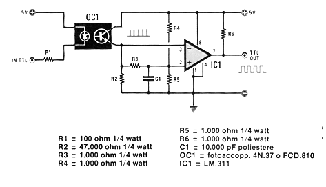
6. The Shield with an Optocoupler
This circuit gives us an idea of how we can use a coupler with a transistor to interface with a TTL input or a microcontroller. The power must be supplied at 5 V and the driver input can come from any logic circuit of 3.3 or 5 V with the use of R1 of appropriate value. The power must be supplied with 5 V and equivalent operational amplifiers can be used.
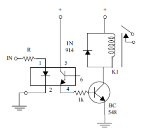
7. The Shield with an Optocoupler and a Transistor
This circuit was obtained in my book Mechatronics Sourcebook. It shows how to use a common optical coupler like the 4N25 to trigger a relay, in an application like an isolated optical shield. The driver transistor is the BC548 or the equivalent and relays from 6 to 24 V can be controlled. The advantage of this circuit is that the ground of the coupler LED emitter can be different from the ground of the drive with a transistor, ensuring insulation between the circuits. The resistor can be of 220 Ω or less for microcontrollers with 3.3 V output and 330 Ω for 5 V outputs.
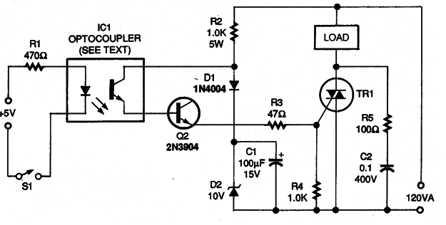
8. Insulated Power Shield for Triac Trigger
Like most shields this consists of a solid state relay (SSR) resulting in an isolated shield. The transistor can be the BC548 and the Triac any of the TIC series according to the supply voltage and current of the fed load. The optocoupler can be any one which has a phototransistor as an internal sensor. The Triac must be equipped with a good heat radiator. The circuit is for 110 V and 220 V, according to the Triac. The circuit can be controlled by the TTL and CMOS outputs with the change of R1 when necessary. Instead of S1 the signal may come from a microcontroller with the use of R1 of appropriate value.
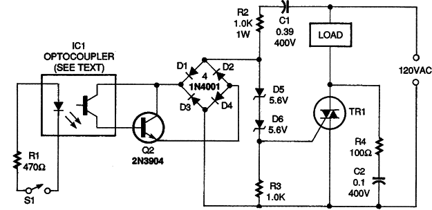
9. The Insulated Power Shield for Triac Trigger (II)
This shield or solid state relay (SSR) was found in an Electronics Now edition of 1995. The transistor can be the BC548 and the Triac any of the TIC series according to the supply voltage and current of the fed load. The optocoupler can be any one which has a phototransistor as the internal sensor.The Triac must be equipped with a good heat radiator. The circuit is for 110 V and 220 V, according to the Triac.The circuit can be controlled by microcontrollers, TTL and CMOS outputs with the change of R1, when necessary.
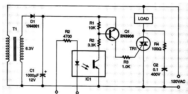
10. The Insulated Power Shield for Triac Trigger (III)
This relay circuit or solid state shield (SSR) is from an Electronics Now edition of 1995. With it we can connect power loads using CMOS or TTL input signals. Sometimes R2 should be changed according to the trigger signal. TR1 can be any Triac from series TIC with a current according to the load and voltage according to the power supply, which can also be 220/240 V. The transistor can be the BC558 and the transformer 6 V x 100 mA or more. In this circuit we have a circuit which derives the control voltage from the power grid so that it is DC to power the coupler. The Triac must be equipped with a heat radiator. The resistor must have its value according to the type of control signal.