PWM
One of the main applications for microcontrollers is on the control of engines.
As we have seen in other chapters of this book, the PWM control is especially important in its characteristics of better performance and torque maintenance.
Thus, the most common microcontrollers have PWM outputs, i.e., outputs that can be programmed to provide PWM control signals for engines.
In practice they can not be connected directly to a motor, because their current is very low, but they can be used to control shields with the ability to handle the high currents of a DC motor.
In Figure 1 we have an example of a PWM DC motor control shield using an H bridge which also enables a reversal of its direction of rotation from microcontroller commands.
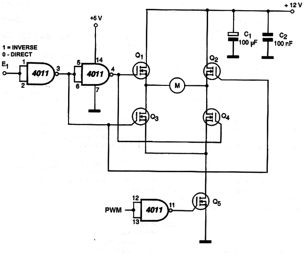
Other features can be found in many microcontroller families for specific applications such as radio signal transmitters and receivers (Wi-Fi), and much more.
Architecture
The several circuits which form a microcontroller are organized in a very definite ways and there are variations for this. The way the many circuits are interconnected and as they run is called the "architecture" of the microcontroller.
Most microcontrollers use two main architecture types on their chips: RISC and Harvard.
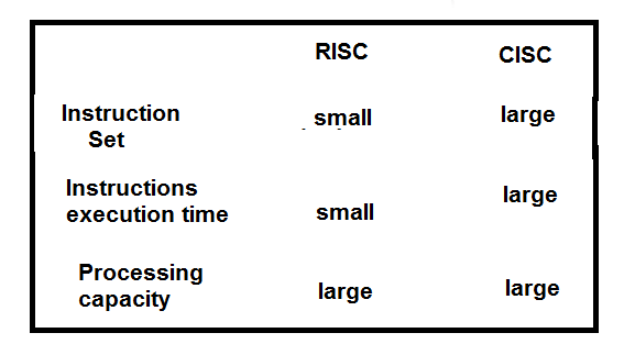
RISC means Reduced Instruction Set Computer. In this type of architecture, the microcontroller does everything with few basic instructions that are matched according to what it needs to do.
The use of few instructions in the RISC architecture makes the microcontroller very fast, so each one can typically run in one clock cycle.
In contrast to the RISC architecture there is a CISC (Complex Instruction Set Computer) that uses a lot of instructions to operate. These computers are more powerful, but slower by the accuracy of several clock cycles to perform some instructions. (Figure 2)
Instructions and Clock
The instructions are the orders that the microcontroller obeys and in its function does something. The clock is the operating rhythm of the microcontroller. A clock oscillator determines the speed with which the microcontroller operates.
Another type of architecture used in microcontrollers is Harvard.
In Harvard architecture, both the program and the data can be stored in the same memory space, which facilitates the operation of the input and output circuits, but they use different buses, that is, separate input and output circuits.
The first computers used one type of architecture called Von Neumann, named after its creator, one of the pioneers of computer construction. In this type of architecture, each instruction could only be executed after an earlier one was completed. The computers of the most modern architectures are parallel, that is, two or more instructions can be executed at the same time, if one does not depend on the other.
External circuits
The integrated circuit consisting of a microcontroller can not do everything by itself. Even when built on a board with basic features like the power supply, and some basic support components, the microcontroller still can not do it all alone.
For it to be used in practical applications there are two possibilities.
The first is to do the application design in which we program the integrated circuit on an external programming board, as the one shown in Figure 3 and then put it on the final board where it has the support circuits that it needs.
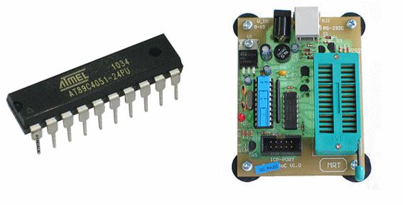
In this way, we have a final product that is a microcontroller being used in an application.
The second is to use a basic board containing the microcontroller and the basic support circuits and connect in its outputs the additional circuits that provide the control signals and are also connected to the controlled circuits, that is, the shields, as shown in Figure 4
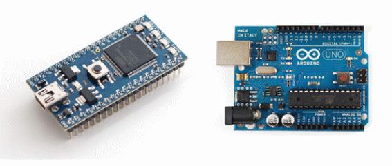
This second way of using a microcontroller is interesting for makers, for didactic and experimental applications as in the case of STEMers.
The boards containing the circuits that provide signals to the microcontroller (sensors, receivers, etc.) are called shields. The boards containing a single component are called breakout boards.
We will deal with them in the next chapter.
Analyzing the characteristics
To correctly use a microcontroller, one must know the main characteristics to verify that they match the project or application.
If you start from an application idea, you should look for one on the available types that has the features you need.
While it is possible to work with microcontrollers of different types, it is easier to rely on a single family for your projects, because you will not only know the features better as the programming language itself.
What we need to know about a microcontroller to use it correctly.
a) Supply Voltage
Most microcontrollers are powered by 3.3 V or 5 V voltages. In boards that include a power supply, a voltage regulator is included, so that at the input we can have a higher voltage range.
For example, the Arduino has an internal regulator which means that it can be powered by voltages from 6 to 20 V. In practice it is recommended not to be less than 7 V and a maximum of 9 V.
The greater the difference between the input voltage and the 5 V output, the greater the heat generated when in operation.
Alkaline batteries or small sources can be used with currents in the range from 250 mA to 1 A. Figure 5 shows examples of Arduino microcontroller sources.
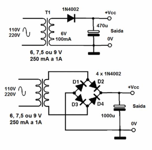
Some microcontrollers, such as the Arduino, have 3.3 V outputs.
b) Consumption
Consumption also depends on what is being controlled by the microcontroller.
Taking into account only the microcontroller the currents can vary from a few milliamps for types of low consumption up to a few tens of milliamps.
The current of the controlled loads must be added when the source is sized.
However, for both the voltage and the consumption it is always necessary to consult the datasheet of the microcontroller used.
c) Processing speed and processing power
The processing speed of the microcontrollers depends on the type and it can usually be evaluated by the clock frequency.
However, we must be aware that the clock frequency does not indicate exactly how many operations a microcontroller makes per second, since there are operations (instructions) which require more than one clock cycle to be performed.
For example, if to make a sum the microcontroller needs to load the numbers to be summed in two cycles and then make the sum in a third, we have an operation that makes use of 3 clock cycles.
Another way to specify speed is in MIPS (Mega Instructions Per Second) or millions of instructions per second.
For simple applications in robotics, speed is not important.
More important when the project requires more than one microcontroller is its processing power given by the number of performance bits.
Thus, the microcontrollers can be 8 bits, 16 bits and 32 bits.
The number of bits determines the complexity of the instructions it performs.
d) Input signals
The microcontrollers, as we have seen, have input pins for connecting control devices such as switches, sensors and circuits that can provide information to be processed.
In the case of analog input pins, the limit is usually the supply voltage, i.e., they can receive voltages from 0 to 5 V, which are converted internally to the digital form and then processed.
In a microcontroller like the Arduino Uno there are 6 analog inputs.
For the digital inputs, the same output pins are normally used, that is, I/O (Input/Output), which can reach 14 as in Arduino.
These pins can receive digital signals TTL or CMOS with voltage of 5 V.
Some of these pins have the ability to work with PWM signals and their quantity varies, depending on the type of microcontroller.
e) Output Signals
For the output we have pins that can supply currents which depend on the voltage. Thus, for the voltage of 5 V the maximum current can reach 20 mA, as in the case of the Arduino.
Thus, the microcontroller will not be able to control anything that requires larger current without the use of an additional external circuit, that is, a Shield.
For microcontrollers that have 3.3 V outputs, the current can reach 50 mA, as in the case of the Arduino.
For this microcontroller there are pins where 3.3 V signals are available.
We can also find types where there are analog outputs that can have the available voltages programmed. Everything depends on the type, and the datasheets must be consulted.
However, before connecting any load to a microcontroller output, you should consult your data sheet to know its limits.
f) Memory
In most simple applications, the programs used with microcontrollers are small. However, it is always important to know what memory capacity the microcontroller used has.
This amount is given for the three types of memory that the microcontroller has: SRAM, Flash and EEPROM.
For typical 32 kB Flash memory types (where the program is running) is an acceptable value.
g) Additional Resources
Today, the device designer using microcontrollers can rely on a wide variety of types ranging from the simplest with basic features to sophisticated versions like many additional features important for specific applications.
One feature that may be important in battery-powered applications is the one which takes the microcontroller to a low-power condition (wait or iddle) when it is idle.
The current consumed can fall to a few microampères which, in the case of battery power, means a great durability.
Other features include placing displays on the boards to generate numeric values or even phrases in specific applications, such as message generation, as shown in Figure 6.
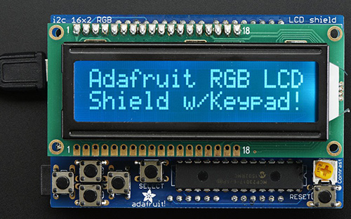
You can also find special types with radio boards (Wi-Fi, Bluetooth) for wireless device communication with mobile phones, internet, etc.
These features are important when the board is used in the development of wireless applications.
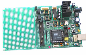
Some didactic boards contain an extension consisting of a region with insulated points of copper forming a universal board where the external control circuits can be built or that must be controlled without the need for shields.
In Figure 7 we have such a board.
Another important feature that must be analyzed in a project is the interruption. There are pins that allow the application of an external signal to stop the execution of the program.