Microcontrollers of 8, 16 and 32 bits are practically the same when it comes to operation. Their main difference is in the amount of information they handle, but how to execute the instructions is very similar.

Most microcontroller manufacturers have adopted ARM microcontrollers as the basis for the manufacture of their products. See in Figure 1. There is a list below of some manufacturers which produce ARM microcontrollers or are licensed to use them.
3Comp
Actel
Alcatel
Analog Device
AppliedMicro
Atmel
Broadcom
Cirrus Logic
Cypress
Ember
Energy Micro
Freescale
Fujitsu
Holtek
Hyundai
HP
IBM
Infineon
Intel
Lapis
LG
Lucent
Marwell
Microsemi
Microsoft
Milandr
NEC
Nitendo
Nokia
Nordic Semiconductor
Nuvoton
NXP
NVidia
OKI Semiconductor
Qualcomm
Sansung
Sharp
Silicon Laboratories
Socle Technology
SONiX
Spansion
ST Microelectronics
Sony
Texas Instrumental
Toshiba
Triad Semiconductor
VLSI Technology
Yamaha
Winbond
WIZnet
Zilog
ZiiLABS
The ARM microcontrollers are 32-bit and for this reason as for now in this article we will refer to them as 32-bit microcontrollers. There are 3 classifications for ARM microcontrollers.
Cortex-M (microcontroller) - It can be used in typical microcontroller applications such as refrigerators, washing machines, remote controls, etc.
Cortex-R (Real Time) - It can be used on MP3 players, engine controls, robotics, etc.
Cortex-A (Application) - It can be used in devices which require operating systems such as cell phones, tablets, computers, etc.
8 AND 32 BIT MICROCONTROLLERS
Figure 2 shows the basic architecture for an 8-bit microcontroller and Figure 3 shows the basic architecture of a 32-bit ARM microcontroller.


Their main differences are in the bus width. In a typical 8-bit microcontroller, the data bus is 8-bit and the addressing bus 16-bit. In 32-bit microcontrollers, both the address and data bus are 32-bit.
What is left remains the same, that is, it has a CPU (Central Processing Unit) program memory, RAM and input and output ports. The way to look for instructions in the program memory and to execute them continues being the same, although the ARM microcontroller, in the hardware level, the search and execution has been optimized.
In ARM processors (Figure 3) we can observe the presence of a bridge in the data and address buses. This is because ARM microcontrollers process instructions at a high speed and peripherals require a lower speed to operate. Thus, we can note that the program memory and RAM are connected directly to the processor and peripherals via the bridge.
Figure 4 shows the common program memory configurations for 8- and 32-bit microcontrollers. In 8-bit microcontrollers it is normal to find program memories of 1 k, 2 k, 4 k, 8 k, 16 k and 32 k bytes. In 32-bit microcontrollers it is normal to find program memory sizes of 128k, 256k, and 512k bytes.

Figure 5 shows the common data memory configurations for 8- and 32-bit microcontrollers. In 8-bit microcontrollers it is normal to find data memories (RAM) of 64, 128 and 256 bytes. In 32-bit microcontrollers it is normal to find 8 k, 16 k, 32 k, and 64 k bytes sizes.


Figure 8 shows data of common integral numbers for 8-bit microcontrollers and Figure 9 for 32-bit microcontrollers.In 8-bit microcontrollers it is common for these data to range from 0 to 255 or 0 to 65 535. In 32-bit microcontrollers these data range from 0 to 4 294 967 295. Here again we have a question of magnitudes and adaptation to the decimal of 32 bits consisting of 4 bytes.


Figure 10 shows input and output configuration records for 8-bit microcontrollers and Figure 11 for 32-bit microcontrollers. In 8-bit microcontrollers these registers are 8 bits while in 32-bit microcontrollers they are 32 bits. Here is also a matter of adapting and viewing and reading the 32-bit registers, in other words put into practice.


The CPU
Figure 12 shows the basic configuration of a CPU for 8-bit microcontrollers, where it is common to have an accumulator, one or more auxiliary registers, an indexing record that is normally used to index data, mainly to store the return addresses when they are called the subroutines, a program counter (CP) and a status register.

Figure 13 shows the basic CPU configuration for 32-bit microcontrollers, usually consisting of 16 32-bit registers, numbered from r0 to r15, and registers for the status of the running program. The records r0 to r13 are used for general purposes, and may be accumulators, records for indexing or indirect routing, data. The r13 is used to point the stack pointer. The link register r14 is used to store the return address when subroutines are called. The r15 register is used as the program counter. It also has a status record.

Memory

In Figure 15 we can see a memory map for a 32-bit ARM Cortex-M3 microcontroller, where the lower part of the memory map is used for the code, following the internal RAM, peripherals, RAM External devices, peripheral buses, and an area used by the manufacturer. Here it is also a matter of practicing to visualize and understand the memory map of 32-bit microcontrollers.

ARCHITECTURE.
Figure 16 shows the block diagram of a basic configuration of an 8-bit microcontroller. In the diagram we can note the CPU, program memory, RAM or data, peripherals or inputs and outputs. The most common peripherals in an 8-bit microcontroller are: General Purpose Input Output (GPIO), interruptions, timers, the watchdog, ADC or the analog-to-digital converters.
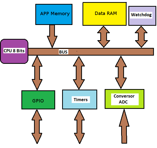
Figure 17 shows the block diagram of the basic configuration of a 32-bit microcontroller. It also has: CPU, program and data memory, peripherals or inputs / outputs. We can note that it has GPIO, interruptions, timers,the watchdog, ADC or analog-to-digital converter, I2C interfaces, SPI, UART, USB, CAN, Ethernet.
In Figure 17 we can see the existence of the two so-called buses:
AHB or the Advanced High-performance Bus
APB or the Advanced Peripheral Bus

As discussed earlier, two buses are used because of the peripheral work speed that is much smaller than the operating frequency of the CPU and memories. For example, while the CPU and memories may be working at a frequency of 72 MHz, the peripherals can work at 36 MHz. In some ARM microcontrollers, the APB bus is divided into 2 buses (APB1 and APB2). This is done because some peripherals are slower than others.
One of the properties of the ARM microcontrollers is that for each peripheral it is necessary to enable its clock pulse and its voltage so that they can work. By default all the peripherals are without voltage so that the current consumption of the system is the smallest possible. Figure 18 shows how the system clock is enabled for each peripheral by an AND gate. Without this capability, read and write operations on the peripheral have no effect.

We are now able to understand a diagram of an ARM microcontroller. Figure 19 shows the block diagram of an ARM Cortex-M3 controller, specifically the STM32F103xx manufactured by ST. We can see that the maximum frequency of the AHB bus is 72 MHz. The buses APB1 and APB2 can operate at different frequencies.

The APB1 bus can operate at a frequency between 24 and 36 MHz and the following peripherals are connected to it:
TIM2
TIM3
TIM4
USART2
USART3
SPI2
I2C1
I2C2
CAN
USB
SRAM
WDG
The APB2 bus can operate at a frequency between 48 and 72 MHz and the following peripherals are connected to it:
WAKEUP
GPIOA
GPIOB
GPIOC
GPIOD
GPIOE
TIM1
SPI1
USART1
ADC1
ADC2
Temperature Sensor.
Figure 20 shows the schematic diagram of the STM32F103C8T6 microcontroller. We can observe the relationship between the peripherals and the pins.

EXAMPLE PROGRAM
It's time to understand how we can program the microcontroller. Most ARM microcontroller manufacturers provide users with function lists to use the peripherals (Library). In many microcontrollers it is necessary to create this functions.
In 8-bit microcontrollers to write AND in a port it is typical a line of code like:
P0 = counter;
To read a port, it is typical a line of code like:
temperature = P2;
In 32-bit microcontrollers this is done through functions that the manufacturer itself provides to be used by the programmed ones. For example, to write at a port it is used:
GPIO_WriteBit (GPIOA, GPIO_Pin_6, 1);
The previous line of code will write a logic 1 (high level) at pin 6 of port A.
For a port on a 32-bit microcontroller we can use a line of code like the following:
pushbutton = GPIO_ReadInputDataBit (GPIOB, GPIO_Pin_0);
The previous line of code reads pin 0 from port B. As we can see, it is easy to use these functions to read or write at the ports. Depending on the manufacturer of the microcontroller, the name of these functions may vary but are usually similar.
The following program is a simple example program to turn on and off an LED intermittently.
int main()
{
Init_IO();
while(1)
{
GPIO_WriteBit(GPIOA, GPIO_Pin_6, 1);
delay_stm(1000);
GPIO_WriteBit(GPIOA, GPIO_Pin_6, 0);
delay_stm(1000);
}
}
The Init_IO() function is responsible for enabling and configuring port A and their respective clocks. The Delay_stm(1000) function retards the microcontroller in 1 second. This function receives a parameter in milliseconds. 1 000 = 1 second.
The following is an example program to turn the LED on and off, when the pushbutton P1 connected to pin 0 of port B is pressed.
int main()
{
Init_IO();
while(1)
{
If ( GPIO_ReadInputDataBit(GPIOB, GPIO_Pin_0) == 0 )
{
GPIO_WriteBit(GPIOA, GPIO_Pin_6, 1);
delay_stm(1000);
GPIO_WriteBit(GPIOA, GPIO_Pin_6, 0);
delay_stm(1000);
}
}
}
To edit the code for ARM microcontrollers there are many tools such as LEIL, IAR, etc. Figure 21 shows the KEIL compiler development interface.

Analyzing the little we've seen so far, programming an 8-bit microcontroller and a 32-bit microcontroller is pretty much the same. The difference is in the magnitude of the data, its processing speed is much greater, its greater number of peripherals. In the next articles we will program the peripherals and make useful projects to get started in programming ARM microcontrollers in a simple and easy way to understand.