The dual drive of power loads can be performed with several circuit configurations. These configurations are interesting solutions both when using discrete logic circuits in simple designs and microcontrollers, acting as shields.
In this article we present solutions that are basically applied to solenoids, however, they can also be used with any kind of power load sensitive to polarity or motion.
Double Solenoid Actuators
Two solenoids can be used in a simple arrangement for a direction control, as shown in Figure 1.
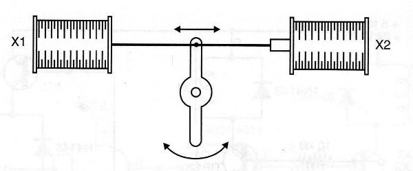
When X1 is triggered, the lever is pulled in one direction and when X2 is triggered the lever moves in the opposite direction.
The system can be coupled, for example, to a control wheel, thus changing the direction of a robot.
Another possible application is shown in Figure 2, in which the drive of one or the other solenoid moves an object in two possible directions.

Note that in this type of application the two solenoids can not be energized at the same time. This is a prohibited condition which must be avoided.
Following are some practical circuits for solenoid actuation (and as indicated in the introduction) they can also be used with other types of loads requiring alternating triggering.
Intelligent control for two solenoids
The circuit shown in Figure 3 uses power transistors of complementary types and is designed in such a way that it avoids the prohibited state of drive at the same time of the two solenoids.
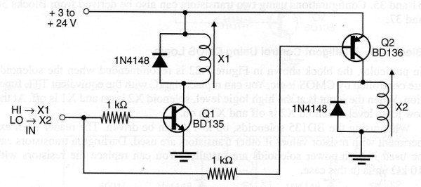
When the input is at the high logic level, or receives a signal of at least 1 V, or solenoid X1 is energized while the solenoid X2 remains de-energized. When input goes to logic low or 0 V, solenoid X1 turns off and solenoid X2 switches on.
The transistors are chosen according to the load current, or the controlled solenoids. For BD135 and BD136 the maximum current is around 500 mA.
The 1 k resistors can be reduced to 330 ohms in the case of activation by the output of microcontrollers. Note that the supply voltage of the circuit do not necessarily need to be the voltage of the microcontroller.
This voltage which can vary between 3 and 24 V is the voltage required for the solenoid drive, or another controlled load.
Smart shield for solenoids using Darlington transistors
The same configuration seen in the previous item can be elaborated with complementary Darlington transistors, as shown in Figure 4.
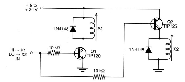
This configuration has a higher sensitivity and can be operated with a much lower current. In this case, a few milliamps are needed to control two solenoids with currents of the order of up to 1 A.
In particular, this configuration is indicated for driving from CMOS logic, TTL and the output of microcontrollers.
As a shield, the 10k resistor may eventually be changed depending on the signal level obtained and the solenoid power may be different from that used for the microcontroller.
Smart Shield Using CMOS Logic
In Figure 5 we have a control circuit using CMOS logic. In this case too, the forbidden state is avoided, and the transistor depends on the drive current of the solenoid used.
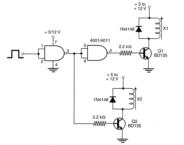
The integrated circuit must be powered by the same voltage as the microcontroller.
For BD135 transistors the maximum current of the solenoid is 500 mA, but TIP31 can be used for currents up to 1 A, and Darlingtons pairs for larger currents.
The Shield with CMOS and Power MOSFETs
High current solenoids can be controlled with the circuit shown in Figure 6.
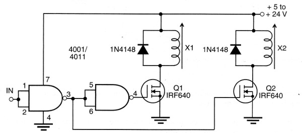
In this case too, if the circuit is used as a shield, the power of the 7 pin of the CMOS must be the same as that of the microcontroller. For MOSFETs the voltage must be in accordance to the solenoids or controlled loads.
For high currents, the MOSFETs must be built on good heat sinks.
Conclusion
The circuits we have seen can be modified in a number of ways, for example with the use of complementary configurations, additional transistors for better driving and more.
Other possibilities include the use of mechanical means for returning solenoid cores when they are not interlocked, as shown in Figures 1 and 2.
Magnetized cores with the same purpose can also be used. Anyway, what we have seen are basic ideas that can be used in the most diverse projects.