Everyone knows microcontrollers cannot do everything on their own. They are just the brain of a smart project, such as those which can be created currently based on Arduinos, MSP430, PIC, ATMega and many others.
For the complete design, you need to have the "muscles" which will perform the operations determined by the "brain", such as moving parts, producing sounds, triggering LEDs and more.
Likewise, microcontrollers need "sight”, "hearing”, "touch”, and many other senses that we humans do not have such as perceiving atmospheric pressure, infrared radiation, RF, and more.
Thus, it is necessary to rely on circuits which do this, they are the so-called shields or interfaces or breakout boards that can be acquired ready, but also built easily on small boards or breadboards.
Here are a few of our circuits which can easily be used in these functions, some requiring only minor adaptations, or as a basis for a sensational smart project, for your graduation work or to create a product that gives you money.
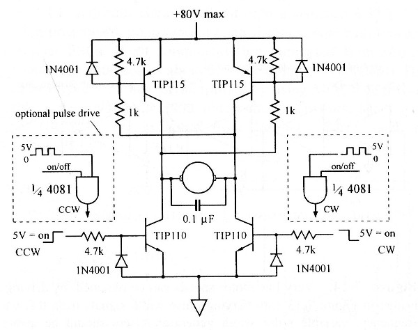
Bi-directional Motor Shield with MOSFET
This circuit was obtained from an American publication on DC motors. MOSFETs must be chosen according to the power of the controlled motor and built on heatsinks. The supply voltage of the bridge may be different from that of the control logic.
Common transistors such as BC548 and BC558 can be used instead of the originals.
The maximum motor current controlled depends on the MOSFETs used. The circuit is for 5 V logic, but can be modified by reducing the 10 k resistor to operate with a 3.3 V logic.
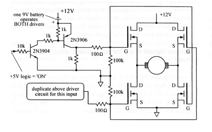
Bridge H Shield For the DC Motors Control
This other circuit was obtained from an American documentation about motors. The circuit accepts equivalent transistors according to the power of the controlled motor. The motor voltage does not have to be the same as that which powers the control logic which makes it possible to use it with microcontrollers.
Note that the circuit is suitable for supplying high voltage motors. Transistors must be provided with excellent heat sinks. The maximum motor current is 1 A.
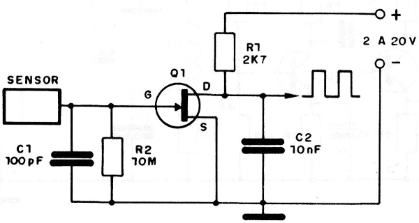
JFET Touch Shield
This circuit can be used as a shield for a touch control. The circuit can use any common FET such as BF245 and should never be powered by a transformerless source. The circuit is from a documentation about JFETs.
The sensor consists of a small metal plates and the wire connecting it must be short, so that it does not function as an antenna by picking up noises that will erratically trigger the circuit.
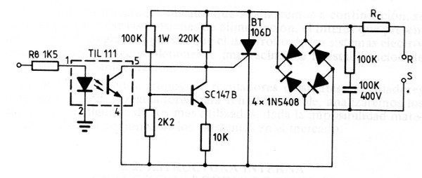
Solid State Relay Shield
This circuit shows how to implement a solid-state control shield for an SCR connected to the power grid. The bridge diodes should be in accordance with the load current.
The resistor in series with the LED can be 270 ohm or 330 ohm microcontrollers of a 5 V output and other optical couplers with transistors can be used.
For a 3.3 V logic the resistor can be 47 to 100 ohm, depending on the optical coupler used.
The transistor may be BC547.
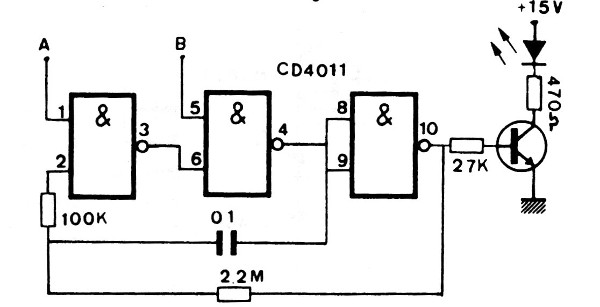
4011 Signaling Shield
This circuit causes an LED to blink at a frequency determined by the capacitor C1. The circuit can be powered by voltages of 3 to 15 V and the resistor indicated depends on the current in the LED and can be changed. The 4011 power pins are not indicated. The circuit is controlled by pins A and B and to be used as a shield the power must be 5 V.
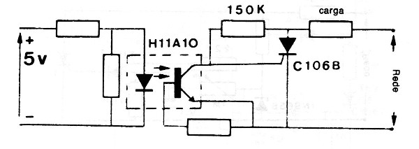
Shield For SCR
This insulated shield uses a common optical coupler which supports multiple equivalents. The resistor in series with the emitter LED can be of 330 ohm to 5 V and the resistor in parallel can be omitted in most cases. The circuit is from an old documentation and the resistor between the base and the emitter is typically 10k.
A SCR shall be provided with a heatsink according to the controlled load.
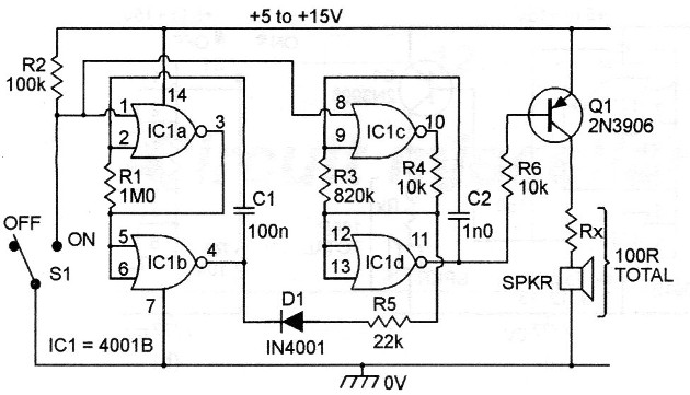
Two-tone Siren Shield
This circuit can be controlled by pin 1, by the output of a microcontroller functioning as a shield in a warning or alarm system.
The circuit may have higher power by changing Q1 through a BD136 and removing resistor Rx so that only a low impedance speaker can be used.
The transistor, in this case, may have a separate higher voltage source. For a shield the CMOS power supply must be 5 V.
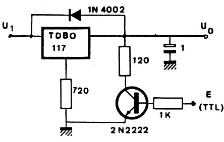
Controlled Voltage Regulator Shield
With this circuit a logic output signal from a microcontroller or other digital TTL configuration can control the supply voltage to a load. The cut is not complete because the voltage remains at 1.25 V minimum. The regulator is according to the desired voltage.
In order to obtain the cutoff at zero volts, the regulator reference pin must be supplied with a -1.2 V negative supply.
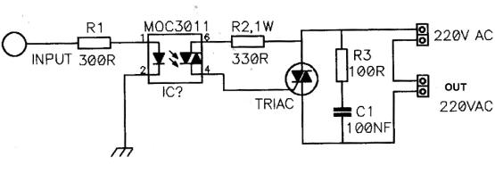
Isolated Shield for a Triac
This isolated shield for a triac was found in an old European documentation. The resistor R1 can actually have values ??between 270 and 330 ohms for microcontrollers with 5 V outputs. The triac can be TIC226 built on a heatsink, depending on the current of the controlled load.
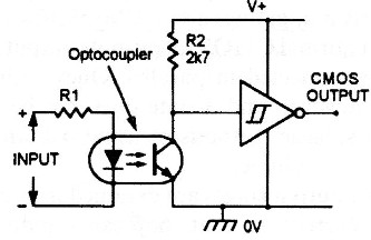
Input Shield with Optocoupler
Settings like this can be found at various points on this website. The trigger port can be a 4093 with the inputs attached, functioning as an inverter. The power supply is dependent on driven logic, usually 5 V for microcontrollers. The coupler can be of any type and R1 depends on the signal source.
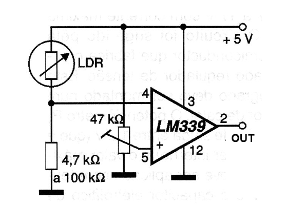
Optical Sensor Shield
This traditional sensor configuration with LDR was found in a 2001 documentation. The integrated circuit is a voltage comparator and the trigger adjustment is done at the trimpot. The power can be made with voltages of 5 to 12 V allowing its use as shield for microcontrollers.