Optical Sensor Shield
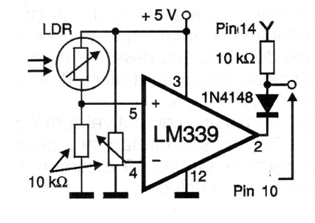
Originally, this circuit from a 2000 documentation was created to operate as a sensor for the parallel port, however it can be used as a shield for microcontrollers with few modifications. The sensitivity adjustment is done at the 10 k trimpot. The sensor is a common LDR.
The same circuit can be used with other resistive sensor types and the voltage comparator can also be LM139 or LM239.
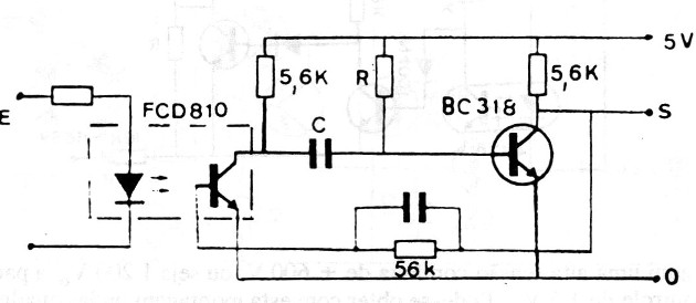
Monostable Optical Shield 1
A new monostable optical shield configuration is shown below. The time at which the output signal is present is determined by the capacitor C. The optical coupler accepts equivalents and in the driving by a microcontroller a resistor of 120 to 330 ohm in series with the output must be provided. The circuit is from an old French documentation. The transistor can be 2N2222.
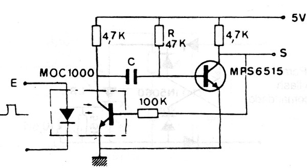
Monostable Optical Shield 2
The capacitor C and the resistor R in this circuit determine the time the output is at the high level after receiving a command from the optical coupler. The resistor in series with the emitter of the coupler can be 330 ohm for the 5 V microcontrollers and 120 ohm for the 3.3 V output. The circuit is from an old French documentation. The transistor may be BC548.
Sensor Front Detector Shield
This circuit, obtained from an old technical documentation, shows how to use logic functions to detect the front or the rising edge of a logic signal. The circuit can be implemented with any logic and C depends on the signal rise time, having a typical value in the range of 100 pF and 1 nF.
Tone Detector Shield
This Shield recognizes the signal of a certain frequency (up to 100 kHz) obtained from a receiver, changing the level of its output from top to bottom. We can use it on a remote control or a micro-controlled automation or even on a security link by a micro-controlled tone. The 5000 ohm or 4k7 potentiometer controls the sensitivity of the circuit.
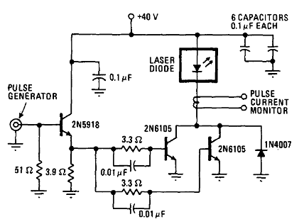
Laser Diode Modulator Shield
This circuit is from a telecommunication documentation from 1976. The circuit can modulate the LASER in an optical data communication system with a microcontroller. The transistors can be 2N3055 for 2N6105 and 2N2222 for the input transistor.
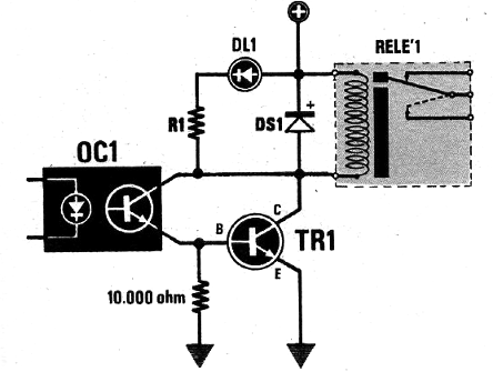
Isolated Relay Shield
This circuit was found in an Italian magazine, 1986. It shows how the optical coupling must be made to drive a relay with total insulation from a microcontroller. TR1 can be BC548, R1 depends on the coupler being able to have values between 47k and 47k and DL can be any LED. The supply voltage depends on the relay. A 120 ohm or 220 ohm resistor should be connected in series to the LED depending on the output being either 3 or 5 V.
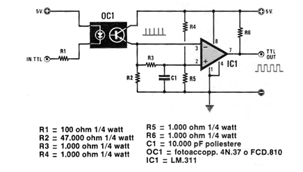
Shield with an Optical Coupler and a TTL Output
This circuit came out in an Italian publication from February, 1986. This publication no longer exists, but the circuit gives an idea of how we can use a coupler with a transistor to interface with a TTL input. The power must be supplied at 5 V and the driving input can come from any logic circuit. The power must be supplied with 5 V and equivalent operational amplifiers can be used.
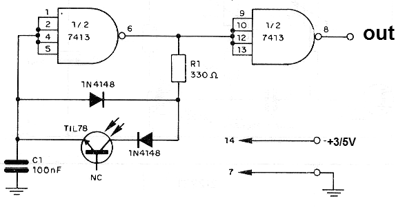
Light Sensor Astable Shield
This circuit can be used as a light intensity to a digital converter in a micro-controlled sensor system. The frequency of the circuit shown depends on the intensity of the light incident on the phototransistor. The central frequency band, determined by C1, with the indicated component values ??is around 5 kHz. The circuit should be powered by 3 or 5 V voltage and other NAND ports or inverters can be used as the 7400.
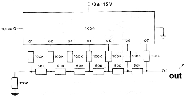
Digital to Analog Converter Shield
This circuit produces an output voltage which depends on the number of pulses applied to its input. The circuit has 7 bits which provides a scale of voltages of 128 degrees. The power can be made with voltages from 3 to 15 V and as the output impedance is too high, the output voltage must be amplified by the operational connected as the voltage follower. The accuracy of the output voltage depends on the accuracy of the resistors used.
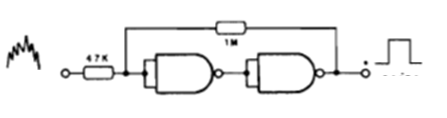
Schmitt Anti Bounce Trigger Shield
A positive feedback resistor of 1 M makes two common NAND ports of a 4011 integrated circuit into a trigger, with action which eliminates bounces in signals with fast variations such as sensor contacts, etc. The circuit can be powered with voltages from 3 to 15 V and operates in frequencies up to about 10 MHz depending on the supply voltage.
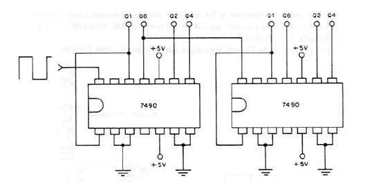
Counter Shield up to 99
The figure shows how to connect the TTL 7490 integrated circuits for counting up to 99. Counted values appear in BCD form at outputs Q1 to Q4 of each integrated circuit. These signals can be taken to a decoder and displayed. See in CIR001 the complete circuit for this purpose. The circuit must be powered with 5 V and the input signal must be rectangular, free of scratches. More 7490 integrated circuits can be cascaded to count up to 999, 9999, etc. We can use this circuit as an external counter for pulses of a microcontroller output, if we do not want to use other outputs for this purpose.
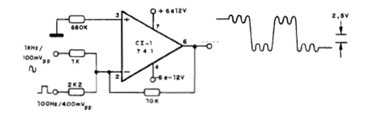
Linear Combiner Shield
This circuit combines two signals, one being a 100 Hz rectangular and the other 1 kHz sine wave. We can use it to combine the rectangular signal of an Arduino or another microcontroller with an external signal, or even another digital signal from another microcontroller output. The power supply must be symmetrical and equivalent operational amplifiers may be employed. In the input there can be added other signals, taking into account the amplitude, and its action given by the values of the resistors in series. Remember that the circuit does not operate with signals beyond 100 kHz. Based on the Fourier theory we can add more inputs and generate signals of complex waveforms from a microcontroller.
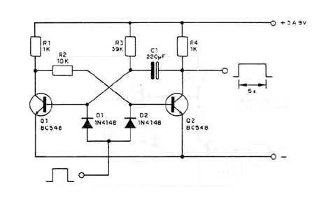
Transistorized Monostable Shield
A pulse applied to this circuit causes it to switch and remains in the new state for a time determined by R3 and C1. The circuit can be powered by voltages from 3 to 9 V and the triggering pulse should be positive. We can use it to generate a pulse of longer duration than the one obtained from an output of a microcontroller without having to program another output.
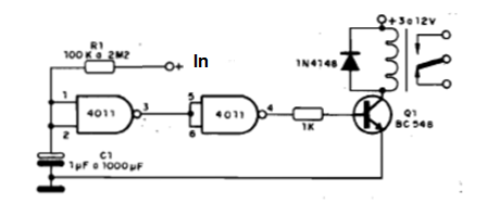
Timer or Integrated Delay Shield
The idea of this Shield is to trigger a relay with a delay after the moment when a certain output of a microcontroller is brought to the high level. This circuit offers a timer from a few seconds to about one hour, depending on the value of R1 and C1. For long periods the capacitor must be of good quality, as leaks can stop the operation of the circuit. The relay can be from 3 to 12 V with a maximum coil current of 100 mA. The integrated power supply is made on pins, 14 (positive) and 7 (negative) with 5 V. 4001 can be used with similar operation. See that the output used must remain at the high level until the moment the circuit is triggered and then for the time that we want it to run.