Translated into English by Patricia Lima Carlos
Digital games have long been our readers' most chosen projects, ranging from the simple transistor technology and simple integrated circuits by driving LEDs or other devices, even TTL and CMOS technology in a more complete way with displays and other features.
We have hundreds of projects on our website which are covered in our books, for the most diverse tastes.
Analyzing these projects, we found that many of them can be improved or even elaborated in a simpler way with the use of microcontrollers such as Arduino, PIC, MSP430 and others which today are cheaper and affordable.
In fact, many of these projects can work as a basis for more elaborate projects, with the basic circuits being used as both input and output shields.
In one of our volumes about the subject in the Circuit Bench series we approached several of these projects. At the time we wrote this article, the book was not released yet, but we will give you several suggestions for game projects which can be improved and if you browse our website you can find more.
In fact, we also have other volume in the Circuit Bench series dealing with shields and many articles on the subject in our microcontroller section.
But the idea is simple: by taking the basic idea of ??a game, for example, an electronic drawer (a number draw circuit which can be used in a bingo game) we see that we have functions like an oscillator which generates a random number of pulses and a counter which feeds a set of displays, 2 in case of numbers from 00 to 99.
Well, we can do a normal microcontroller version if we program the microcontroller to generate a random number of pulses and count them presenting the result in displays which many of the versions already have incorporated.
However, we can go beyond creating more things by taking advantage of the capabilities which a microcontroller has.
For example, one of the functions that a simple digital circuit TTL or CMOS does not have is the ability to memorize the numbers drawn so that the same number is not drawn twice. With a microcontroller, this feature can be added.
Another feature is the ability to transmit the number generated by a Wi-Fi network to mobile phones which downloads an application, that is something more complex and can be very interesting.
It all depends on the designer's knowledge about the microcontroller technology to carry out their project.
Here are some suggestions for projects based on articles that we publish in our section Circuit Bench and in books of the same series.
Project Suggestions
Of course the degree of improvement of each project or even the change of the basic functions will depend on the imagination and knowledge of each one. We just give the suggestions.
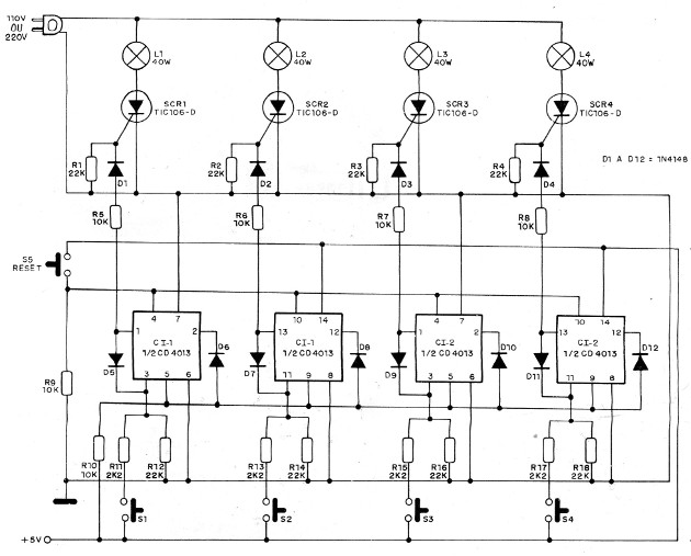
1. Reflex Test
This circuit was found in an 1888 publication. However, as it makes use of common components, it can still be built easily nowadays. In this version, there are 4 competitors and the indicator lamps are incandescent powered by the power grid.
SCRs must have small heat sinks and a separate DC power source must be used for the CMOS. This 6 to 9 V source can be made up by batteries.
One idea is to modify the indicating circuit, changing the SCRs through the inputs of a microcontroller and get the indication of the triggered key in a display and adding more resources.
Among the features which can be added there is a timing to enable the response by triggering a green indicator and an additional timing to ring a beep when the time set for the answer runs out.
With a microcontroller, it is also possible to multiply the inputs and thereby increase the number of the participants with the indication of the corresponding number in a display.
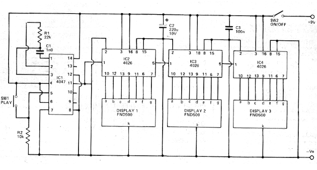
2. Black jack
This circuit came out in a Hobby Electronics magazine from March 1980. The magazine no longer exists, but the circuit is current by the components it uses. By pressing and releasing SW1, the display shows a number between 000 and 999 obtained randomly from the number of pulses generated by 4047.
It is possible to replace the 4047 for an oscillator with 555, with the same results. The displays are of common cathode and the circuit must operate with voltages between 6 and 12 V. The consumption does not recommend the use of batteries, because the displays consumes enough energy.
The idea is to modify the circuit so that it can be microcontrolled. The microcontroller can either be used to drive the display or to create results which are not random or follow different rules than the conventional ones.
Another idea is to program combinations of numbers which are awarded and the prize value can be displayed in LEDs or in a second set of displays.
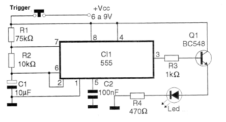
3. A Shot in the dark
In this circuit from 1987, the player has to briefly press one of the keys trying to hit the LED that will be on at the moment. The random oscillator with 555 keeps each output of 4017 activated for a few tens of seconds. The power can be done by 4 batteries or 9 V battery.
The idea is to make a microcontrolled version where the basic configuration can be kept. We can, for example, generate speed signals randomly varied by a microcontroller and add sound effects, when the shot hits the target.
Another possibility is to multiply the triggering of LEDs in a breadboard and generate a target that runs in a board and not in a line.
4. Scoreboard for Foosball
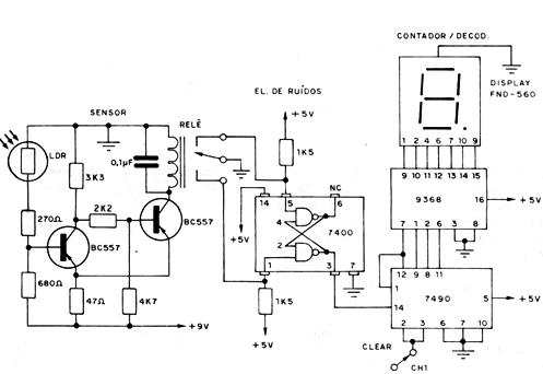
This circuit was found in a documentation from 1981. As you can see, this is a well-designed automatic scoreboard for Foosball matches, in which the passage of the ball through the drawer channel after each goal changes the display number.
Obviously, for a normal application, two units like this one must be built, installing the sensors, one in the passage of each goal. The author suggests that behind each goal you put a tube where the ball passes when falling, and in this tube would be installed the sensor, a LDR which would be illuminated by a small lamp.
The passage of the ball, interrupting the light beam would trigger the circuit changing the score. It is clear that imaginary readers will have other alternatives for the installation of the scoreboard and may even use it in other games or even counting objects, noting that the use of a single display limits its capacity to values from 0 to 9.
The operation of the board explained by the author is as follows: when the sensor light (LDR) is interrupted, a ddp appears on the relay coil which activates the noise eliminator circuit. This circuit consists of two NE ports and a relay of two reversible contacts, its function being to prevent more than one pulse from being generated in the meter with only one pulse in the sensor.
The CH1 (Clear) switch is normally closed, since when it is opened, the count will be reset to zero. Note that in this circuit by the use of the TTL integrated we have a supply of 5 V. For the sensor circuit, however, the supply voltage is 9 V.
The idea here is to transform the circuit so that it is microcontrollable, adding more digits and even programming effects like timing and warning about end of match, greater number of digits, etc.
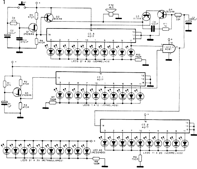
5. Roulette and Dice
This circuit from an old documentation, but with modern components still common nowadays, bringing together two games in one. In one position there is the draw from 1 out of 6 LEDs (Dice) and in the other 1 out of 10 (roulette). The circuit is powered by batteries or a battery.
The idea is to turn the game into a microcontrollable version. The LEDs can be replaced by a display and the oscillator can have special effects and even be programmed for the circuit to work in an "addicted" mode, with the control of the results.
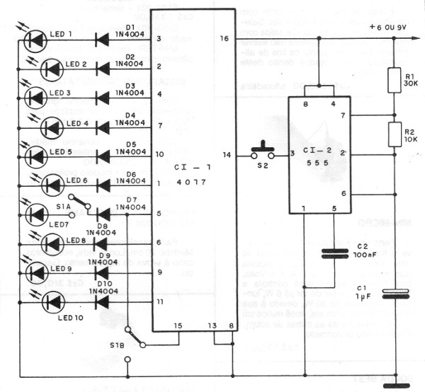
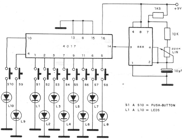
6. Shooting the LED
We present another game whose circuits can be adapted to a microcontrolled version. The drive circuits and some others can be used as shields, and the power supplied with 5 V.
The idea of this circuit is to push the button in such a way that the LED of the horizontal row hits the LED which moves in the vertical row. The circuit has a very interesting effect and can be built in a larger version for parks and theme parties.
The circuit is from a 1988 documentation and makes use of common CMOS components. Given the amount of LEDs triggered and the high consumption, it is recommended to use a source from 5 to 9 V.
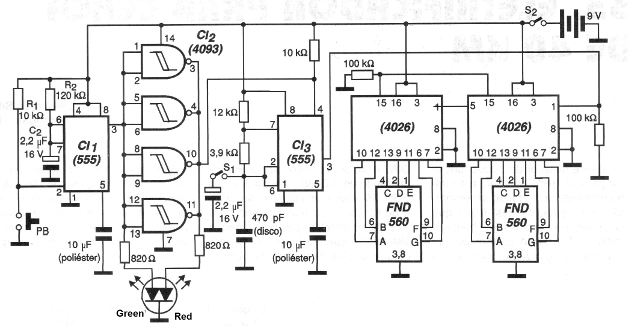
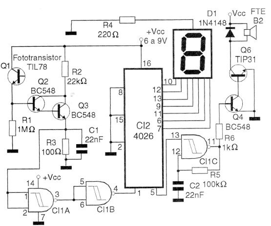
7. Electronic Bingo
Lucky or skill electronic games can be easily modified to operate on microcontrollers. This is one more of them in which parts can be used as shields and the main control and it can be done with a microcontroller.
This 2001 CMOS digital circuit draws numbers from 00 to 99 and can be expanded. However, it does not have the ability to know when a number has already been drawn. In a microcontrollable version this is possible.
Even other features like Wi-Fi transmissions results to mobile phones, it is possible with an application.
The circuit uses common cathode displays and the power is made by a 6 V battery. The use of microcontrollers with displays facilitates the design.
8. Target For Infrared Shooting
This is another game circuit which in the original version was made with discrete components, but that can be done with a microcontroller with the indication of hits by displays and other interesting features. We use the input stage with the sensor to apply its signal to a microcontroller.
The weapon for this target is given in the following circuit. The circuit can be powered by voltages from 5 to 12 V and with 5 V can be adapted to be an Arduino shield where in addition to counting can have more functions programmed. The display is 7 common cathode segments.
9. Weapon For Infrared Shooting
This electronic game was found in a 1996 documentation, but can be easily assembled nowadays, both the weapon and the target given in the previous circuit, since the components used are common. The gun is powered by batteries or a small battery.