The designs described in this selection of articles can be used with microcontrollers or other types of circuits which require isolation. With them we can develop applications in automation, internet of things (IoT), wearable, robotics and much more.
1.Optical Shield
In this circuit the photo-transistor signal is amplified by a Darlington stage and then applied to a trigger stage which controls a relay. The relay triggers when the sensor is illuminated. The sensor can be any ordinary phototransistor and the relay is of the sensitive type for voltages of 12 V with a coil of the order of 220 ohm. The sensitivity of the circuit is determined by the 100 k ohm trimpot setting. The emitter can be an infrared LED controlled by a microcontroller, in an application as a shield. A resistor of 100 to 470 ohm should be connected in series to the emitter LED if controlled by a microcontroller.
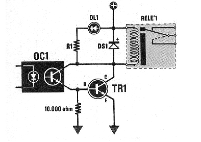
2. Relay Shield with a Transistor
This circuit came out in February 1986 in Nuova Elettronica. It gives an idea of how we can use a coupling with a transistor to drive a common relay. The relay can be 6 or 12 V up to 100 mA, TR1 is BC548 and R1 has values ??between 470 ohm and 4.7 k, depending on the DL1 LED and the relay voltage.
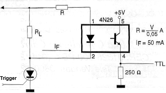
3. TTL Optical Shield
This coupler allows the triggering of a TTL port or flip-flop from an SCR. The resistor R must be calculated by the formula next to the diagram as a function of the supply voltage of the system in order to obtain an LED current of the order of 50 mA. The circuit can be used as an input shield with 3.3 or 5 V supply. It can also be triggered by the output of a microcontroller with the use of R of appropriate value.
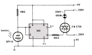
4. Shield Using a Photo-Cell as a Sensor
This circuit was obtained in a French magazine called Radio Plans from January 1985. By the components which it uses it can be built easily still nowadays, being used triacs from the series TIC. The solar cell can be of the type found in calculators and watches. Its driving can be done through a common LED controller by a microcontroller.
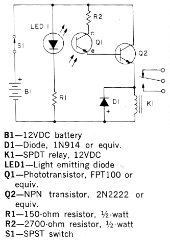
5. Power Shield for Relay or another Load
This circuit was obtained in the publication 101 Electronics Projects from 1979. The circuit can be assembled easily, since all the components are common. When the LED light which strikes the phototransistor is established, by removing an object between them, the relay closes its contacts. The relay can be 6 or 12 V depending on the power, the phototransistor of any type and Q2 can be a BC548. In the case of a shield, the LED can be controlled by the microcontroller and R1 will be 150 ohm for 3.3 V outputs and 330 ohm for 5 V outputs.
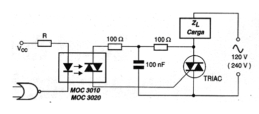
6. AC Shield for the Triac
The circuit shown is for inductive loads. It will also be convenient in this case to use a snubber circuit to protect the TRIAC.TRIACs from the TIC series can be used in this application and for loads smaller than 200 W the resistors can have their values reduced to 22 ohm. Note that it is important to have appropriate value resistors for the TRIAC to switch at the beginning of the half-cycles so that most of the power is transferred to the load. R will be 220 ohms in the case of 3.3 V outputs and 330 ohms to 5 V.
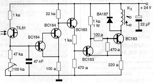
7. Optical Shield for a Relay
This circuit is from an optoelectronic manual from Texas Instruments from 1978. The transistor may be a more modern equivalent, just like the photo-detector. The relay current is a maximum of 20 mA and the power depends on the coil of this component. The triggering can be done by a LED controlled by a microcontroller.
8. TTL Opto-shield
We found this circuit in the Texas Instruments opto-electronics manual. The bipolar can be BC548 and the phototransistor admits an equivalent. As an input shield or sensor, the TTL output signal can be applied to the microcontroller. As an output shield the phototransistor can be part of an optical coupler.
9. Relay Shield with a Comparator
This circuit triggers a relay when light strikes a sensor. As a shield, the LDR can be triggered by a LED controlled by a microcontroller, thus obtaining insulation between the circuits. The sensitivity adjustment is done in the potentiometer. Equivalent operating comparators and amplifiers may be used. The supply voltage must be according to the relay used. The output of LM324 without the relay can also be used in an input sensor shield.
10. Sensitive Relay Shield
The sensitive shield shown in the figure below fires when light strikes the phototransistor. The sensitivity adjustment is done at the trimpot or potentiometer P1. The relay shall be of the sensitive type for 6 V or 12 V with a maximum coil current of 100 mA. Optical features can be used with the photo-transistor to increase sensitivity and directivity. Equivalent types may be used.