The designs described in this selection of articles can be used with microcontrollers or other types of circuits which require isolation. With them we can develop applications in automation, internet of things (IoT), wearable, robotics and much more.
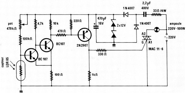
1. Isolated Shield with a Triac and LDR
This circuit was obtained in a French magazine, Radio Plans from January, 1985. By the components it uses, it can be built easily still nowadays, being used triacs of the TIC series. NPN transistors can be BC547 and PN BC558. The LDR is controlled by an LED from a microcontroller, in an application as an isolated shield.
2. Optical Relay Shield
The recommended distance between the emitter and the phototransistor is 10 mm for this configuration. The circuit is suggested by the Texas Instruments opto-electronics manual. The relay must be in accordance to the circuit supply. The emitter can be a high power white LED in series with an appropriate resistor according to the current and voltage of the microcontroller.
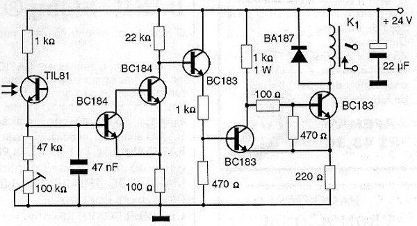
3.Optical Shield
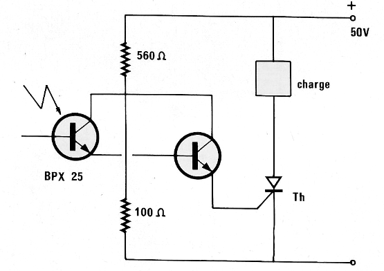
In this circuit the photo-transistor signal is amplified by a Darlington stage and then applied to a trigger stage which controls a relay. The relay triggers when the sensor is illuminated. The sensor can be any ordinary phototransistor and the relay is of the sensitive type for voltages of 12 V with a coil of the order of 220 ohm. The sensitivity of the circuit is determined by the 100 k ohm trimpot setting. To use as shield, the excitation signal comes from a LED controlled by a microcontroller.
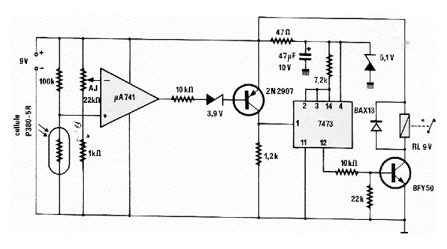
4. Bistable Photo-Shield
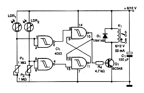
The circuit we present consists of a photoelectric control with bistable action. The circuit can be controlled by two LEDs connected to the outputs of a microcontroller as a shield. A light pulse on LDR2 turns on the relay and a new pulse on LDR1 turns off. The sensitivity is set at the trimpots or potentiometers P1 and P2. The LDRs are of the ordinary round type, and can be installed in opaque tubes with lenses for greater sensitivity and directivity. The relay is of a sensitive type of 6 V or 12 V depending on the voltage used at the power supply. The coil must have a maximum drive current of 50 mA. The connection wires to the sensors (LDRs) can be long, up to 20 meters in length. With the increase of P1 and P2 to 10 M ohm, photo-transistors can be used as sensors.
CI-1 - 4093 - CMOS integrated circuit
Q1 - BC548 or equivalent - general purpose NPN transistor
D1 - 1N4148 - general purpose diode
P1, P2 - 1 M ohm - trimpot or potentiometers
R1 - 2.2k ohm x 1/8 W - resistor - red, red, red
C1 - 1000 uF x 16 V - electrolytic capacitor
K1 - Relay - see text
LDR1, LDR2 - common Round LDRs - DSD4060 or equivalent
Miscellaneous:
Breadboard or printed circuit board, battery or source holder, wires, welding, etc..
5. Relay Shield with a Lock
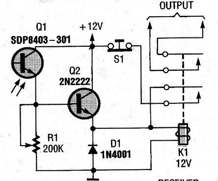
When the sensor receives light, the relay closes its contacts and remains so, even after the light has returned to the sensor. The sensitivity is set at R1 and the circuit can either be powered with 6 V or 12 V depending only on the relay used. We found this circuit in an American publication from 1993. The phototransistor can be controlled by the pulse produced by an LED at the output of a microcontroller, thus obtaining a perfectly isolated shield.
6. Shield for a Relay or Load with SCR
This circuit was obtained from an Electronque Loisirs magazine from France issued in July, 1991. Here we have a setting for triggering an SCR with a phototransistor. The SCR can be TIC106 and the transistor BC548. The trip can be done by an LED powered by the output of a microcontroller for an application as a shield. The supply voltage must be according to the load.
7. Relay Shield with a Darlington Transistor
The photo-trigger circuit shown in the figure has enough power to drive a 12 V relay with current up to 2 A. Other loads, such as motors and solenoids, can be used. The phototransistor can be replaced by equivalents. Note the inverted polarity of the power supply and diode, since we are working with a Darlington PNP transistor. For currents above 100 mA on the drive, the transistor must be equipped with a heat radiator.
8. Optical Shield with an LDR
This circuit was obtained in a French magazine, Radio Plans from January, 1985. By the components it uses, it can be built easily nowadays. The NPN transistor can be BC547 and PN BC558. The circuit can be powered from 6 to 12 V depending on the relay used. The LDR is driven by an LED from a microcontroller.
9. Shield with a Trigger
The circuit shown is suggested by Texas Instruments in its opto-electronics manual. The maximum distance between emitter and sensor is 1.5 cm and the power determines the relay used. In a modern application with a shield, a LED in series with a resistor is used, controlled by the output of a microcontroller.