All instructions of a microcontroller can be classified into 3 main classes:
1 - Instructions of conditional jump.
2 - Instructions of memory (variable movements).
3 - Arithmetic and Logical Instructions.
In this article we will study and put into practice the Instructions for Data Movement in Memory. Starting to program microcontrollers may seem like a task which requires a lot of knowledge, but with Arduino, we will started in developing designs and circuits using microcontrollers, in an easy and fun way. The first thing we need to know is how a microcontroller is inside, what parts it is assembled, how it works and what the relationship it has with the compiler or the programming language.
PARTS OF A MICROCONTROLLER.
There are three main parts of a microcontroller:
1 - The memory.
2 - CPU or Central Processing Unit.
3 - The Peripherals.
Figure 1 shows the main parts of a microcontroller.
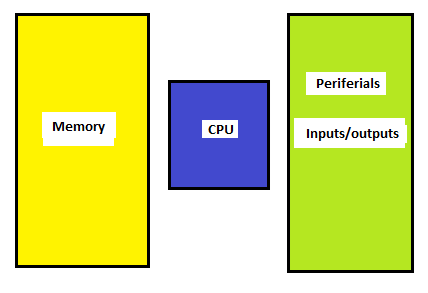
Memory is the part of the microcontroller responsible for storing instructions and data.
The CPU is the part of the microcontroller which is responsible for executing the commands or instructions of the program written in C language.
A peripheral is the part of the microcontroller which is responsible for removing or inserting information or data from the outside. Usually, it is known as I / O.
MEMORY
To understand memory, we can make an analogy between it and the human mind. The mind stores information or data; The same is true for digital memory, it is used to store information or data. We can represent a memory as a series of drawers or drawers where information is placed.
In digital electronics, there is a circuit called flip-flop type D or date, this circuit stores information after receiving a digital pulse. Figure 2 shows a scheme of this circuit. What this circuit does is to read the logic level present at the input D and when a pulse is received by the Clock input it stores it at output Q.
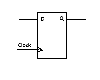
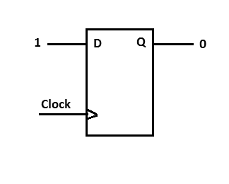
Figure 3 shows an example of the circuit, in a certain state, before receiving a pulse at the Clock input. In this state, output Q is at logic level 1 (high) and the input at logic level 0 (low).
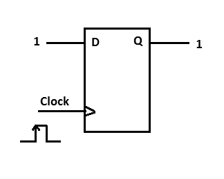
Now, if we take a positive (high) pulse at the clock input, the logic level at input D is stored in the flip-flop and its value is displayed at output Q. We can see this in Figure 4.
Now, we can assemble a circuit which has 8 D-type flip-flops which is shown in Figure 5.
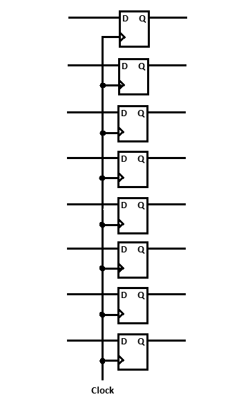
We have 8 D inputs and 8 independent Q outputs. The clock is in parallel with the 8 flip-flops. The operation is exactly the same for the 8 flip-flops, as explained above for a single flip-flop. This type of circuit is called a register. Figure 6 shows an example in a possible state of this circuit, before receiving a pulse through the Clock input.
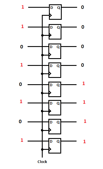
Figure 7 shows the circuit after receiving a positive pulse at the Clock input. The values are stored in the Q outputs.

Thus, we can store data or digital information. There are several digital circuits which incorporate several flip-flops and follow the operation explained above.
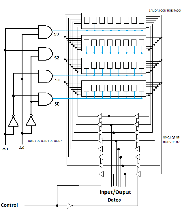
For assembling a memory, we can join several flip-flops, organized as shown in Figure 8.
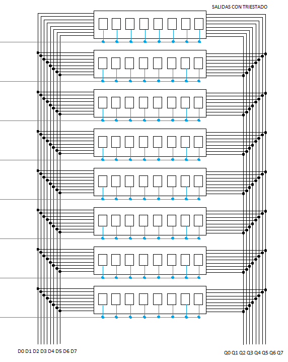
The data is put at the D0, D1, D2, D3, D4, D5, D6 and D7 inputs. The data is stored in the respective group of flip-flops and displayed or removed by the Q0, Q1, Q2, Q3, Q4, Q5, Q6 and Q7 outputs. Since all outputs Q are in high impedance, i.e. in high impedance state, there are no problems with short circuits and only the selected register will be present at the output Q
What we need now is one way to select each record. For this, we can use a digital circuit called decoder. This circuit is made up of some digital NOT and AND ports. Figure 9 shows the logical operation of a NOT (inverter) port. This circuit reverses the logic level present at the input.
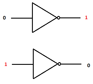
Figure 10 shows the logical operation of an AND gate. This means that only when all its inputs are at the logic level 1 (high), its output is set at logic level 1; otherwise, its output will have a logic level of 0 (low). With these components, we can form a decoder.

Figure 11 shows a decoder with 2 inputs and 4 outputs. Note that when the inputs are at the logic level 0, the inverters (negators) select the first output. Now let's add the decoder to the registers so that you can select the desired one.
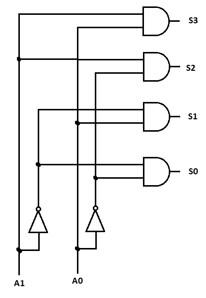
Figure 12 shows the circuit.
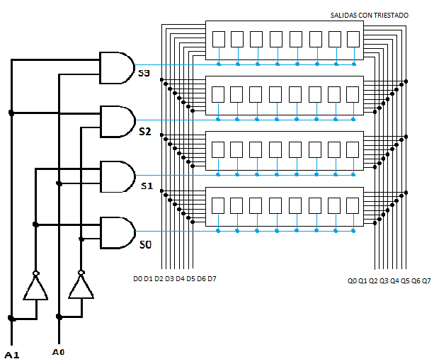
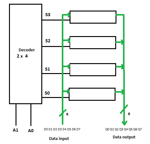
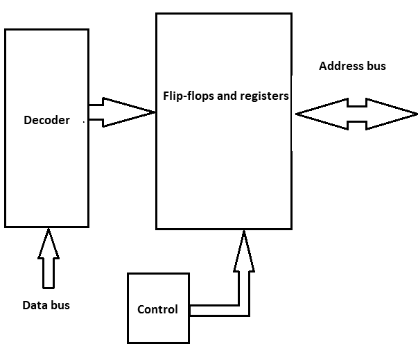
Figure 13 shows the block diagram of the circuit of the figure.
Now we need a circuit which allows us to use the input and output data bus on a single bus. For this, we will use a tri-state buffer (Transceiver). Figure 14 shows how a pair of the Tri-State buffers allows us to use the same digital line so that at one instant it is input and at another instant the output.
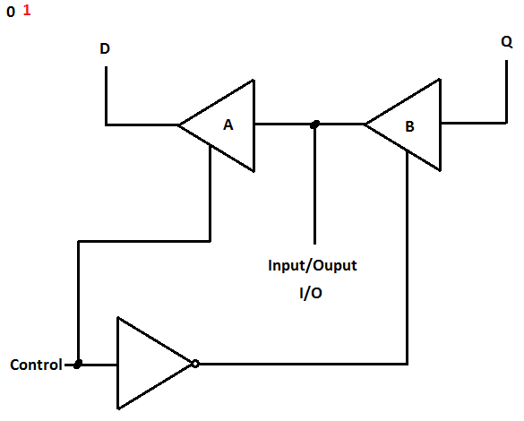
When the input level on the control line is at 0, the port output does NOT reverse to logic level 1 and selects the tri-state for the buffer B, which causes the value of Q to appear on the line I / O. When the control line is logic 1 and the gate reverses, logic 0 will be present, disabling the Tri-State B buffer. But now, buffer A is activated, so that the logic level present on the I / O, is available on the line A.
Based on this principle, we can make a control circuit for the circuit of Figure 12. The circuit of Figure 15 presents this circuit and Figure 16 shows its respective block diagram.
PROGRAM AND DATA MEMORY
The microcontrollers have a memory for storing instructions called program memory. In it, the instructions are stored sequentially. The Central Processing Unit (CPU) looks for the instructions in this memory and executes them. See Figure 17.
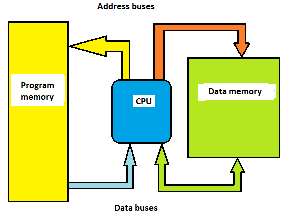
The data is stored in the data memory. The data are values which can vary during the execution of the program, so they are called variables.
The memory of the program is non-volatile, that is, when the microcontroller is disconnected from the power supply, the information remains. As for example, ROM, PROM, EPROM, EEPROM, FLASH, etc. The data memory is volatile, which means that when the power supply is disconnected, the information is lost. As an example we have dynamic RAM (DRAM) or static RAM (SRAM).
Memories are built with different types of arrays or architectures, but regardless, they all store the information and their operating principles are the same.
THE COMPILER AND THE DEVELOPMENT ENVIRONMENT (IDE).
The compiler is the publisher where the programs are made. It is primarily a text editor and instructions are written sequentially, depending on the mode you want the microcontroller to execute. In the Arduino development environment (IDE), the main() function is called automatically. The main function calls the setup() and the loop() function. But most books and microcontroller texts use the main() function, so to understand better how the memories work inside the microcontroller, the following explanation will help.
The code starts to run in a function called main(). The following is the code for this function:
int main ()
{
}
You should assign names to data memory addresses before this function. For example, the next line tells the compiler to separate the byte in the data memory and assigns the name count.
unsigned char count;
The following line of code tells the compiler to write the value 9 to the memory address count.
int main ()
{
count = 9;
}
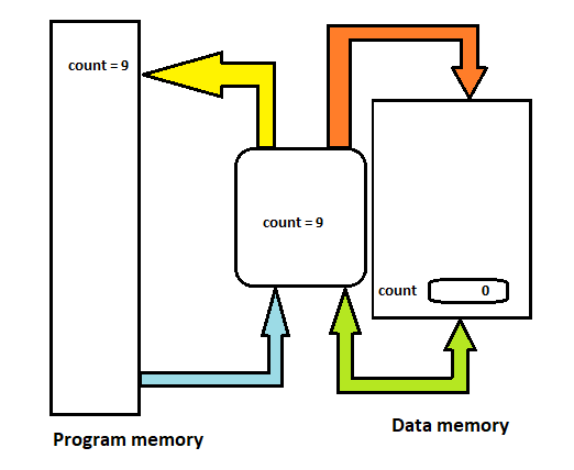
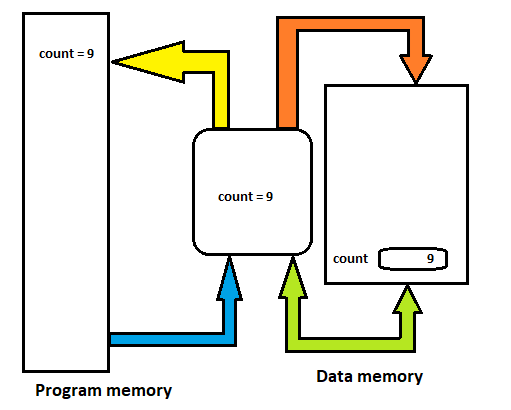
In Figure 18, we can see what happens before executing the instructions.
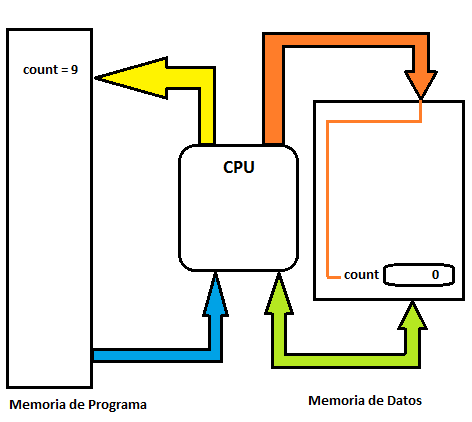
Figure 19 shows when the CPU reads the instruction and Figure 20 after executing the instruction.
In the following example, we will have 3 positions in the data memory:
unsigned char count;
unsigned char temperature;
unsigned char humidity;
The following code assigns values ??to these memory locations. For memory pocketing count is assigned the value 7, for the memory temperature position, the value 22 is assigned and for the memory position of humidity is assigned the value 16:
usigned char count;
usigned char temperature;
usigned char humidity;
int main()
{
count = 7;
temperature = 22;
humidity = 16;
while(1)
{
}
}
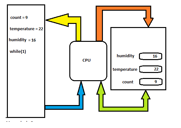
See Figure 21 to understand what happened in the data memory. The while instruction (1) is an infinite loop which currently does nothing.
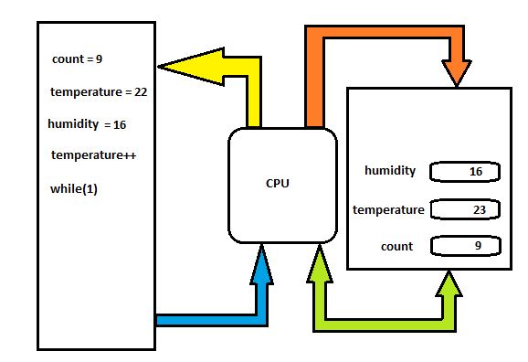
In the following example, we will perform a variable temperature increment statement. The instruction:
temperature ++;
In other words, after the program started running, the variable temperature will remain at the value 23. Figure 22 shows this example.
usigned char count;
usigned char temperature;
usigned char humidity;
int main()
{
count = 7;
temperature = 22;
humidity = 16;
temperature++;
while(1)
{
}
}
THE OPERATOR OF ASSIGMENT (=).
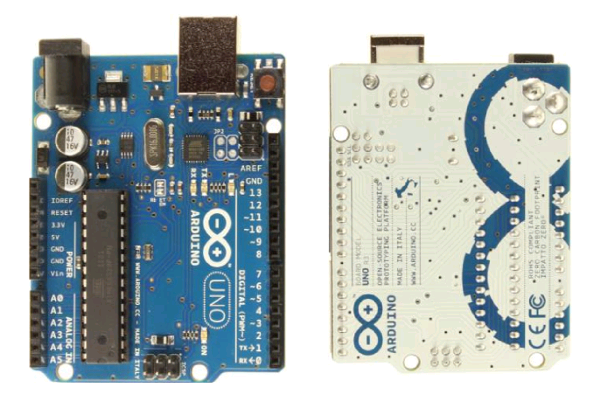
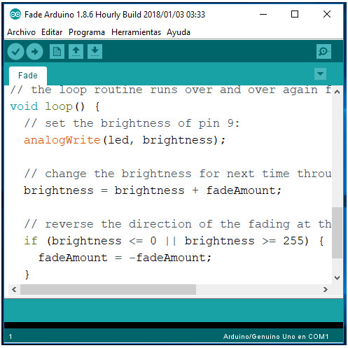
In Figure 23, we can see the Arduino Uno board and in Figure 24 the IDE or development environment, which can be downloaded from the Arduino website. To assign a value to a variable, we use the assignment operator (=). In the following example, the sensor variable is stored in the display variable.
display = sensor;
In the previous instruction, the value contained in the sensor variable is moved or transferred to the memory location of the display. For example, suppose the value of the memory location display is 27 and the value of the display variable is 9. After the instruction display = sensor; the value of the display variable will be equal to 7. Thus, it is how we move data from one memory location to another or from a gate to the memory or the memory to a port.
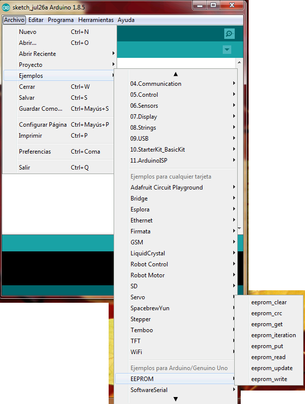
The C language uses the assignment operator (=) to transfer data from one memory location to another. In addition, there are functions ready to be used, as in the case of EEPROM memory. The following are the functions to record and read in this memory. The sample codes can be found on the menu: Files-> Examples-> EEPROM. See Figure 25.
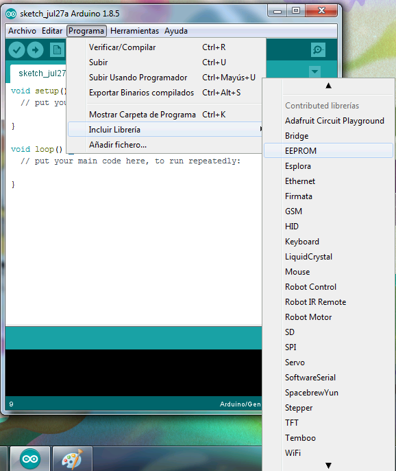
If you want to include the library in any design, go to the menu: Program-> Include Library-> EEPROM. For this, see Figure 26.
THE INSTRUCTION FOR WRITING IN THE EEPROM MEMORY (EEPROM.write)
The EEPROM.write instruction allows you to write a byte into the EEPROM memory. For this we use the write function as follows:
EEPROM.write (address, value)
Parameters:
address: the location to be written, from 0 (int)
value: the value to record from 0 to 255 (byte)
Return: none
In the following example, we store the values read from the analog input 0 in the EEPROM memory. These values will remain in the EEPROM memory when the circuit is turned off and can be read by another program. Figure 27 shows the circuit used for this program.
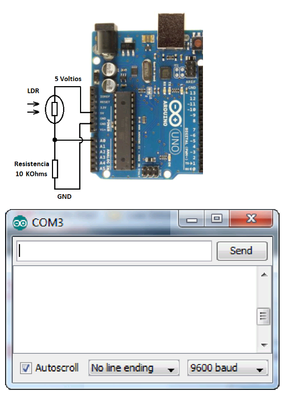
The program can be found on the menu: Files-> Examples-> EEPROM-> eeprom_read.
#include
/** the current address in the EEPROM (i.e. which byte we're going to write to next) **/
int addr = 0;
void setup() {
/** Empty setup. **/
}
void loop() {
/*** Need to divide by 4 because analog inputs range from 0 to 1023 and each byte of the EEPROM can only hold a value from 0 to 255. ***/
int val = analogRead(0) / 4;
/*** Write the value to the appropriate byte of the EEPROM. these values will remain there when the board is turned off. ***/
EEPROM.write(addr, val);
/*** Advance to the next address, when at the end restart at the beginning. Larger AVR processors have larger EEPROM sizes, E.g:
- Arduno Duemilanove: 512b EEPROM storage.
- Arduino Uno: 1kb EEPROM storage.
- Arduino Mega: 4kb EEPROM storage.
Rather than hard-coding the length, you should use the pre-provided length function.
This will make your code portable to all AVR processors.
***/
addr = addr + 1;
if (addr == EEPROM.length()) {
addr = 0;
}
/*** As the EEPROM sizes are powers of two, wrapping (preventing overflow) of an EEPROM address is also doable by a bitwise and of the length - 1.
++addr &= EEPROM.length() - 1;
***/
delay(100);
}
INSTRUCTIONS FOR READING A BYTE OF THE EEPROM MEMORY (EEPROM.read)
The EEPROM.read instruction allows you to read one byte from the EEPROM memory. If by any chance the memory location is read, it has never been recorded, the value returned is 255 or 0Xf in hexadecimal. The format of the read instruction is as follows:
EEPROM.read (address)
Parameters:
address: the location to be read from 0 (int)
Return: The value stored in the location (byte)
The following program reads the values ??of each byte in the EEPROM memory and prints them on the computer. This requires opening the serial monitor. You can find this program in the menu: Files-> Examples-> EEPROM-> eeprom_read.
#include
// start reading from the first byte (address 0) of the EEPROM
int address = 0;
byte value;
void setup() {
// initialize serial and wait for port to open:
Serial.begin(9600);
while (!Serial) {
; // wait for serial port to connect. Needed for native USB port only
}
}
void loop() {
// read a byte from the current address of the EEPROM
value = EEPROM.read(address);
Serial.print(address);
Serial.print("\t");
Serial.print(value, DEC);
Serial.println();
/***
Advance to the next address, when at the end restart at the beginning.
Larger AVR processors have larger EEPROM sizes, E.g:
- Arduno Duemilanove: 512b EEPROM storage.
- Arduino Uno: 1kb EEPROM storage.
- Arduino Mega: 4kb EEPROM storage.
Rather than hard-coding the length, you should use the pre-provided length function.
This will make your code portable to all AVR processors.
***/
address = address + 1;
if (address == EEPROM.length()) {
address = 0;
}
In conclusion, we can see that in order to transfer data from one memory location to another, we use the assignment operator (=). To transfer data to the EEPROM memory, we can use functions such as EEPROM.write or EEPROM.read. This makes it easier to transfer or move data between memory locations.