We do not intend to give a complete design in this article, but rather ideas for assembling a plasma speaker or ionophone based on circuits which we have on the website.
The idea of the plasma speaker is simple. A spark or electric arc ionizes the air causing waves of compression and distension of the air, that is, sounds. This is what happens with lightning and any other "noise-making" electrical spark when it occurs.
It is denominated the state of the matter where the "plasma" air happens, because it is a gas in which the electrons of the atoms have been lost. The substance, in this case the gas, becomes the conductor of the electric current.
Thus, one can obtain the sound reproduction by a spark simply by modulating it with an audio signal.
The great advantage of this type of configuration lies in the fact that it does not use moving mechanical parts, as with a common moving coil speaker.
A first possibility, shown in Figure 1, is to directly modulate the signal of a high frequency and high voltage oscillator with an audio signal.
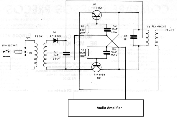
In this circuit, the output of an audio amplifier is connected through a transformer appropriate to a high voltage oscillator.
The capacitors C2 and C3 are sized so that the oscillator noise does not appear on the reproduced signal.
Thus, simply put a spark-igniter on the fly-back output, it will produce the spark and reproduce the sound of the amplifier. See what experiments must be done in order to achieve sound volume and fidelity.
At this point is where the creativity of the assembler comes in.
Another interesting possibility is to make the modulation of the spark through an additional electrode, as shown in Figure 2.
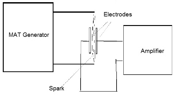
The arrangement and shape of the electrodes should be obtained experimentally. On the internet, we have some circuits and interesting designs which can be improved.
In Figure 3, we have another circuit from our website which can be used in experiments.
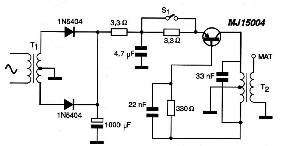
This circuit generates voltages of tens of thousands of volts for designs like electrostatic filters and physics experiments. The T1 transformer has a secondary of 24 V with a current of 3 A and the transistor must be equipped with an excellent heat radiator. The T2 transformer is an old TV fly-back in which we have coiled as primary 10 + 10 turns of ordinary twenty-two, hard wire with plastic cover. The 3.3 ohm resistors are wire and the high voltage can exceed 30 000 volts, so great care is needed in the use of such device.
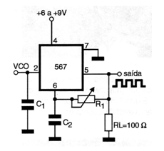
Finally, in Figure 4, we have an interesting circuit which admits the direct modulation by the 567, since this component has a pin for this purpose.
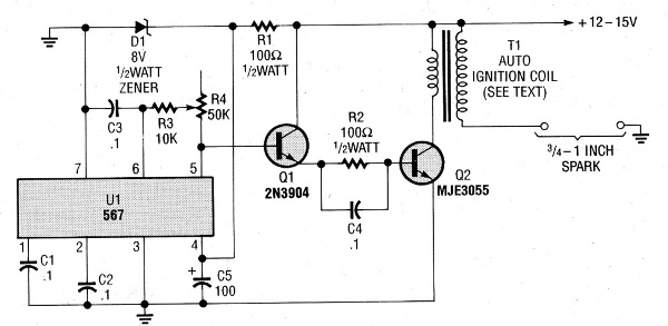
Pin 2 can be used in the modulation, as shown in Figure 5.
Conclusion
Testing new configurations, whether to learn something or eventually create a commercial product, deserves attention.
The suggestions given in this article may be helpful to readers who wish to explore this field.


