
This circuit is both simulation of the operation of a diode bridge and a test circuit for this type o configuration. The circuit uses a 60 Hz x 10 Vpp sinusoidal signal to test the bridge. The wave shape in the circuit is displayed in the virtual oscilloscope of the MultiSIM. Figure 1 shows the circuit.

Figure 1 – Test circuit
The next figure shows the wave shape for a perfect bridge and for a bridge with one diode open
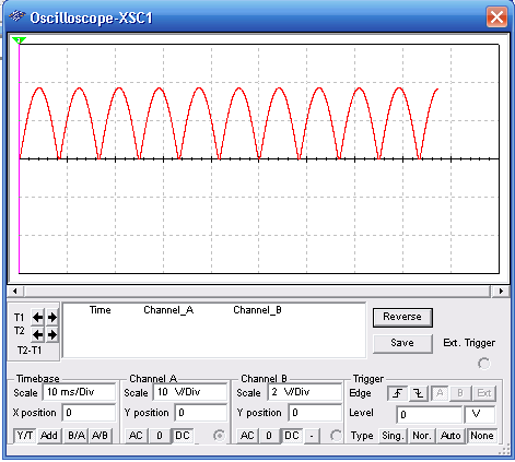

Wave shapes in the circuit
Download the simulation files and Netlist - click here (msb0077.zip)


