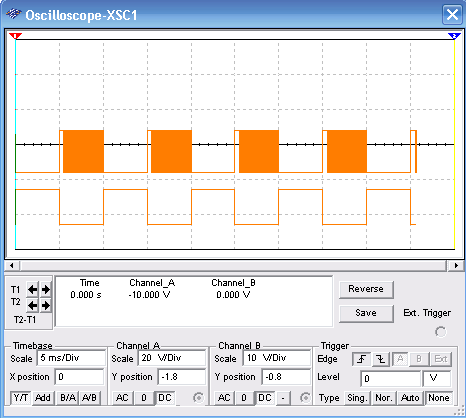
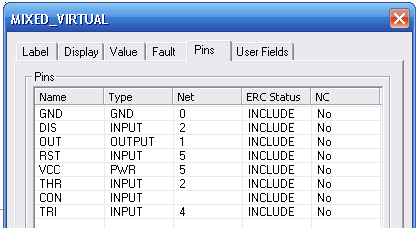
This circuit shows how to control an astable configuration using the 555 IC. The control signal is produced by the function generator (1 to 10 Hz) and the main signal (square) is determined by the 47 nF capacitor and the 10k resistor. These components can be changed. In the figures below we have the wave shape displayed by virtual oscilloscope of the MultiSIM and also pinout for the 555.
To download the simulation files and Netlist - click here (msb0119.zip)