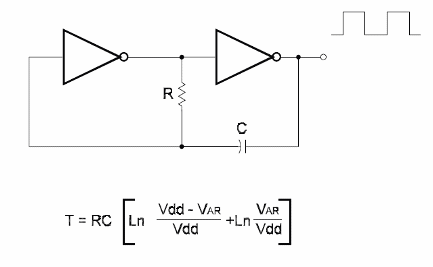
Figure below shows the basic configuration of a ringoscillator using CMOS Iogic. The frequency depends on R'I and C1. R'I must be in the range between 10 k ohm and 22 M ohm. The Iowest value recommended for C1 is 47 pF. The highest frequency produced by this circuit depends on the power-supply voltage, but is generally about B megahertz Any inverten such as the ones suggested earlier in this section, wiII operate in this circuit. The figure also shows the waveforms in the main points of the circuit. When producing Iow-frequency signals, Schmitt Trigger de- vices are recommended. In the formula:
T is the period in seconds [s]
R is the resistance in Ω [0]
C is the capacitance in Farads
Vdd is the power-supply voltage [V]
Vtr is the transfer voltage [V]


