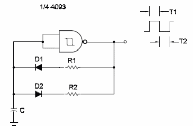
The duty cycle of a Schmitt Oscillator can be programmed by R1 and R2 in this circuit. The frequency of the circuit shown here is determined by the two resistors and 4093. D1 and D2 are general-purpose silicon diodes, such as the 1N914 or 1N4148. The time the output is “1l " depends on R1 and C. The time the output is “0" depends on R2 and C. The circuit can be based on the Schmitt NAND gates of a 4093 or inverters of a 40108. The formulas for the periods given in previous circuits in this section be used to calculate T1 using R1 and T2 using R2.


