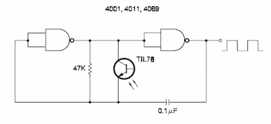
This circuit uses a phototransistor as sensor. The changes in the resistance of the transistor, based on the light falling onto it, alter the mark of the signal and also the final frequency. Any phototransistor can be used in the circuit shown here. It is also possible to use an LDR. The capacitor and R1 determine the central frequency of the circuit. With the values given in the diagram, the signal will be in the audio band [1 kHz to 10 kHz].


