
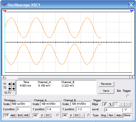
This circuit produces two signals with inverted phases. One is taken for the emitter of Q1 and the other can be taken from the collector. The signal have the same amplitude. In the simulation using the MultiSIM BLUE, the input signal is a sine 1 kHz 200 mV produced by the function generator. Other common general-purpose NPN transistor can be used. The circuit us powered from a 12 V power supply. See the adjustments for the Oscilloscope to display the waveshapes in the circuit.

Figure 1 – Phase Inverter using one transistor
To download the simulation files and Netlist - click here (msb0024.zip)


