

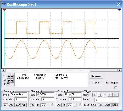
The circuit shown by figure 1 consists in a Schmitt-Trigger using two common general purpose NPN transistors. This circuit converts sine signals into a square signal. In the simulation by the MultiSIM BLUE the potentiometer adjusts the triggering point. Observe the adjusments of the function generator and the oscilloscope to correct simulation.

Figure 1 – Trigger using 2 transistors
A simulação e a netlist são dadas a seguir para os que desejarem utilizar este circuito em outros projetos ou estudar mais profundamente o funcionamento do disparador.
To download the simulation files and Netlist - click here (msb0025.zip)


