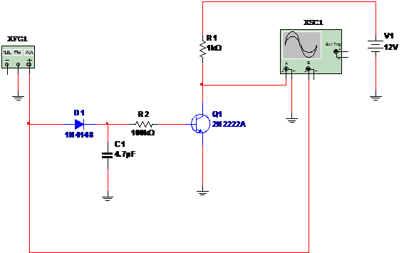
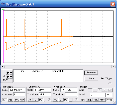
Figure 1 shows a circuit than can be used as time stage in timers, and other applications. Applying a short pulse to the circuit, the output remains high by a time interval determined by C1 and R2. Any general purpose NPN transistor can be used. Try to alter C1 to other times. The performance of the circuit is displayed in the oscilloscope. See the adjustments for this instrument and the Function Generator.


To download the simulation files and Netlist - click here (msb0026.zip)


