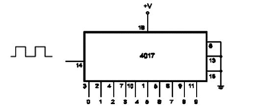
The basic configuration for a 4017 when used as a decade divider with one-of-ten decoded outputs is shown by figure bellow. For each pulse applied to the clock input, one output goes to the high logic level and, at the same time as the previous output, the pulse at the high logic level returns to low logic level. The circuit is reset when “’1" is applied to the HST input. In normal operation this input remains at “0”. The count advances with the positive transition of the clock. The maximum input frequency depends on the power-supply voltage and is 5 MHz with a power supply of 10 V. The circuit advances in the count with the positive transition of the input signal.


