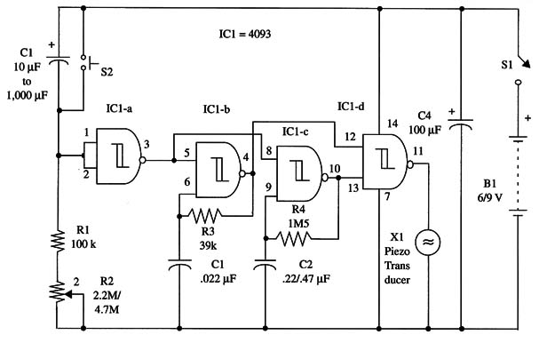
You can use this device as an egg timer or darkroom timer, in games, and in many other applications, as in the case of the preceding projects in this chapter. This circuit will produce an intermittent tone after the adjusted time delay.
Time delays can be adjusted from seconds to more than half an hour.
The circuit can be powered from four AA cells (6 V) or a battery (9 V), and current drain is very low-a few milliamperes at any condition (tone or off).
The circuit can also be mounted on an universal printed circuit board and housed in a small plastic box for portable use.
This version can be used anywhere and transported in your pocket.
A schematic diagram of the pulsed tone timer is given in Fig. 1.

Proper positioning of the polarized components (electrolytic capacitors and battery) must be observed.
Operation of the timer is very easy: first adjust time delay via R2. Then, close 81 and wait.
After the adjusted time, the device will produce an intermittent tone.
To stop the tone, open S1.
To use the unit again, first press S2 to discharge C1, then close S1 to set a new time delay. With a 1,000 µF capacitor (C1) and a 4,700,000 Ω potentiometer, the time delay ranges from seconds to more than half an hour.
IC1 - 4093 CMOS integrated circuit
X1 - Piezoelectric transducer or crystal earphone,
S1 - SPST toggle or slide switch
S2 - SPST momentary switch
B1 - 6 or 9 V (four AA cells or battery)
R1 - 100,000 Ω, 1/4 W, 5% resistor
R2 - 2,200,000 Ω or 4,700,000 Ω potentiometer
R3 - 39,000 Ω, 1/4 W, 5% resistor
R4 - 1,500,000 Ω, 1/4 W, 5% resistor
C1 - 10 µF to 1,000 µF, 12 WVDC electrolytic capacitor (see text)
C2 - 0.022 µF ceramic or metal film capacitor
C3 - 0.22 µF or 0.47 µF ceramic or metal film capacitor
C4 -100 µF, 12 WVDC electrolytic capacitor


