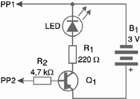
The circuit shown in figure 1 uses a NPN transistor, like the 2SB, BC, 2SA ones or other series. This circuit can be used to test the coils of a transformer, capacitors, lamps, fuses, wires, connectors, loudspeakers, motors, etc.

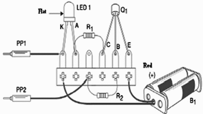
The circuit can be assembled on a terminal strip as figure 2 shows. Other assembling techniques include the use of a printed circuit board or a breadboard. The probes PP1 and PP2, can be a common type used in Multimeters or can be made with two medium sized nails.

LED—Common red LED, or other color
B1— 3 V—2 AA cells with holder
R1—220 ohm x 1/4 W resistor (red, red, brown)
R2—4.7 k ohm x 1/4 W resistor (yellow, violet, red)
PP1, PP2—Probes (see previous text)
Other:
Terminal strip, small plastic box, wires, solder, etc.
Using the Tester
Place the probes on the circuit or component under test. If the LED lights up, the circuit or component under test has continuity (i.e. presents a low resistance). If the LED doesn’t light up, then the circuit doesn’t let the current flow. It is open or it is a component with this property like a capacitor or an isolator.


