This circuit produces separated audible clicks that can be used to get a rhythm when playing a musical instrument, when running or even controlling the way a gymnastics exercise is made. Another use is in scientific experiments or demonstrations where a rhythm must be followed. In a science fair, or a scholar work, the circuit can be used to show the operational principle of common metronomes, including the mechanical type, and how they are used to give rhythm to a musician.
Note: this project was included in my book Science Fair and Technology Education Projects published in USA.
You can also show how the device can be used to determine the speed of a walker or a runner, based in the number of steps by second.
The device is powered by common cells, battery or even an AC/DC converter plugged to the AC power line (any outlet). The selected voltage will determine the volume of the clicks. The only change needed in the circuit is if we intend to power it by a 12 V supply. In this case we must replace the BC558 by a TIP32 mounted on a heatsink. In this case you must also be careful with the terminals placement for this transistor, because it is not the same as the BC558.
The speed of the clicks is adjusted by P1 in a large range of values, but you can also modify the range replacing C1 by other capacitors with values between 2 and 100 ?F.
How it Works
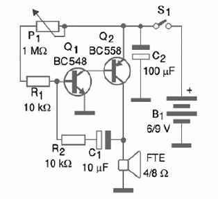
The circuit consists in a low frequency oscillator with two common complementary transistors. The capacitor C1 and the resistor R2 make up the feedback network that keeps the oscillator running by applying part of the output signal back to the input.
These components and P1/R1 determine the oscillation frequency. Since P1 is variable, it allows you to adjust the frequency. The load connected to the collector of Q2 is a loudspeaker that converts the generated electric pulses into audible sound.
Building
Figure 1 shows the complete schematic diagram of the Metronome.

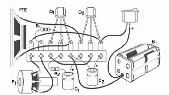
A simple way to make the assemble is by using a terminal strip. Figure 2 shows the components placement on a terminal strip.

The resistors are all rated to 1/8 W or more, having any tolerance and the transistor can be replaced by equivalents. The electrolytic capacitors have a working voltage of 12 V or higher than the indicated in the Parts List. The Potentiometer can be any lin or log type with nominal values in the range between 470 k? ohm and 2.2 M?.
The quality of the sound depends on the size of the loudspeaker. Types between 2.5 cm and 10 cm can be used. The choice depends on the size of the box used to house the device. In the 12 V version the TIP32 must be assembled on a heatsink.
The heatsink is a small metal plate bended to form a ‘U’ or an ‘L’. It is not recommended the use of a 9 V battery, since the current drain is high. Use common C or D cells (6) in this case.
Testing and Using
Testing is very easy. Install the cells inside the holder or turn on the external power supply, observing the polarity. Then adjust P1 to have the desired clicks in the loudspeaker. If you do not find the desired frequency, replace C1. You can add a dial to the Potentiometer based in a common chronometer or even a mechanical metronome.
The scale can be made of clicks or beats by second or in terms of frequency (Hz). For portable applications, for instance, to determine the rhythm of a walker or a runner, replace the loudspeaker by an earphone and power the circuit by 2 AA cells.
Explaining the Project
The builder should find in books or Internet explanations for the use of metronomes in music or other applications. Try to see a mechanical type working and compare with the electronic version. Make an analogy with mechanical oscillating system and electronic oscillator circuits. If you are intending to use in demonstrations, have in hands different values of capacitor to test.
Other Applications
Place the loudspeaker in the horizontal position and put some sheets of paper or small plastic balls on its cone. The balls will jump at each click. Use this effect to explain how the loudspeaker works. You can also connect a LED in series with the loudspeaker, observing its polarity. The LED will produce a flash of light at each pulse.
In a robot or car, the clicks can be used to add special effects, imitating the operation of the motor.
Semiconductors:
Q1—BC548 or equivalent—general purpose silicon NPN transistor
Q2—BC558 or equivalent—general purpose silicon PNP transistor
Resistors: (1/8 W. 5%)
R1 — 10 kohm — brown, black, orange
R2 — 1 kohm — brown, black, red
P1 — 1 Mohm — lin or log—Potentiometer
Capacitors:
C1 — 10 uF x 12 V—electrolytic
C2 — 100 uF x 12 V—electrolytic
Other:
FTE—4 to 8 ?—2.5 to 10 cm—common loudspeaker
S1—On/Off switch
B1—6, 9 V—cells or power supply—option for 12 V AC/DC converter—see text
Terminal strip or printed circuit board, plastic box to house the project, cell holder or power supply, knob for P1, etc.


