This project is indicated for High School and technical courses students. Also, first grades of engineering. Some skill is required to work with electronic circuits
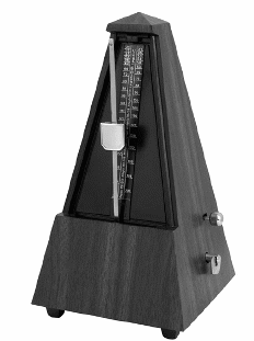
In order to follow the rhythm of music or to give the time to gymnastics movements, some reference is necessary. For this purpose, a device named metronome is used. The mechanical type has an indicator stem that oscillates, setting the rhythm. The adjustment is done in a piece that slides in the stem, giving the speed as shown by figure 1, that illustrates a mechanical traditional type (see MIN52E).

This project describes the simple building of an electronic metronome. It can be used by music students, runners to give rhythm to their steps or even in a laboratory to control dynamic processes.
The circuit produces a sequence of ‘clicks’ or ‘beats’ reproduced by a loudspeaker. The clicks can be adjusted in rates starting from 3 or 4 a second to more than 10 a second. The circuit is powered by sources in the range between 6 and 9 V (according to the desired output power) and all parts are common. You can even use components, like the loudspeaker and the Potentiometer, that can be obtained from non functioning equipments.
How it Works
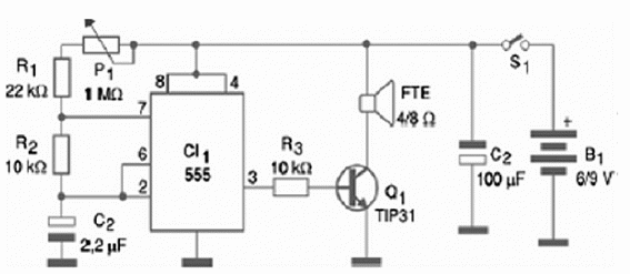
A multivibrator with the integrated circuit 555 has its frequency given by C1, R1, R2 and the adjustment of P1. The square pulses found in the output are applied to a transistor (Q1) that acts as an amplifier.
When powering the circuit by a 9 V supply, this transistor must be assembled on a heatsink. Figure 2 shows the complete diagram for this metronome.

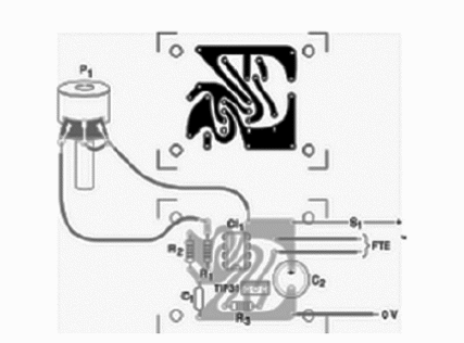
The components are assembled as shown by figure 2. Special care must be taken with the integrated circuit. In order to work safely with this component, we recommend the use of a DIL-8 socket.

P1 is a common Potentiometer, but you can also use a trimmer Potentiometer. Its value is not critical. Values between 1M? and 4.7 M? can be used. Certainly a Potentiometer is the better choice, since it can be installed in a plastic box allowing the external control. A dial can be added to show the beat rate of the metronome. Resistors are 1/8 W or higher dissipation types.
Testing is very easy. Place the cells into the holder and turn on S1. The loudspeaker should produce clicks in a rate that can be changed by P1. If you want a different range of click rates, replace C1. Values between 220 nF and 10 µF can be used. For a higher output power, use a 12 V supply to power the circuit.
Competition:
- Competition involving rhythmic exercises can be programmed using the metronome.
Semiconductors:
CI-1—555—integrated circuit, timer
Q1—TIP31—Power NPN silicon transistor or equivalent
Resistors: (1/8 W, 5%)
R1—22 kΩ—red, red, orange
R2, R3—10 kΩ—brown, black, orange
P1—1 MΩ—lin or log Potentiometer
Capacitors:
C1—2.2 uF—polyester or electrolytic
C2—100 uF x 12 V—electrolytic
Other:
FTE—4 or 8 Ω —small loudspeaker
S1—On/Off switch
B1—6 V or 9 V—4 cells (AA or C), battery with holder or connector
Printed circuit board, plastic box to house the device, knob for the potentiometer, wires, solder, etc.


