High-frequency oscillators may be required in a variety of industrial and consumer applications, such as instrumentation, test bench, etc. Also important are oscillators of this type to repair AM or FM radio sets, receivers, tuners, intercoms, and others. A signal generator capable of producing high frequency signals with good intensity is indispensable. The apparatus described in this article produces a signal of good intensity over a wide range of frequencies and is modulated with an audio tone, which greatly facilitates its use requiring signals of this type.
If the reader does not yet have a small signal generator or even a signal injector, you can’t miss this opportunity to count with the help of this type of equipment from now on. On the other hand if you need a stable circuit for generating high frequencies, this configuration can be very useful.
A simple, fast and efficient process of finding problems on AM and FM radio receivers, intercoms and other communication equipment is to apply an RF signal to your input. By the way this signal, reproduced on the speaker (or earpiece) we can locate the defective stages. This same signal can also be useful for making adjustments to the various stages of equipment of the same type, leading to better performance.
In many articles we have explained how to use the signal injector which, in principle, is the same procedure used for the case of a small signal generator, which means that the reader has several references on this subject. The important thing for the reader now is to have their small generator in the economical version presented in this article or use the basic setting of high frequency oscillator for other appendices.
The circuit shown is basically an audio generator but having a coil tuned at a high frequency, or an RF shock which allows the high frequency harmonics of the generated signal to pass to the external devices being tested. These frequencies can reach values that even allow their use with VHF and even FM short-wave equipment.
The circuit is powered from standard batteries and only two transistors are used. The strong signal can be transmitted wirelessly to receivers that are placed nearby.
HOW IT WORKS
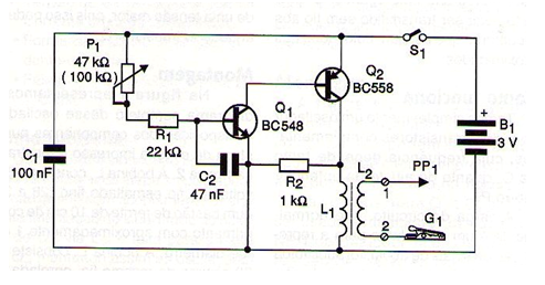
We have basically an oscillator with two complementary transistors whose frequency depends on both C2 and potentiometer P1. The load of the circuit which is usually a loudspeaker for the reproduction of audio signals has been replaced by a coil with ferrite core. In this way, even the high frequency harmonics of the generated signals appear with intensity at the output.
If we want a better coupling with the direct connection of the generator to the test circuit, we can do this through an additional winding placed on the load coil. In this winding we will connect a probe and an alligator clip. The capacitor C32 that determines the frequency of the oscillator can have its value changed over a wide range. The circuit is supplied with 2 batteries. We do not recommend the use of a higher voltage as this could heat the transistor Q2.
ASSEMBLY
In figure 1 we have the complete diagram of this oscillator.

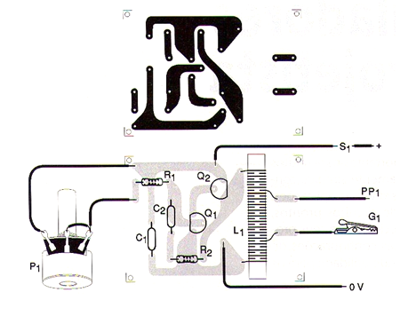
The arrangement of the components on a printed circuit board is shown in figure 2.

The L1 coil consists of 200 turns of fine enameled wire (28 to 32) in a 10 cm long ferrite rod approximately 1 cm in diameter. The coil L2 consists of 30 turns of the same wire, coiled on the side or on L1. The transistors allow equivalents, and the resistors are 1 / 8W with 5% or more tolerance. The capacitors can be polyester or ceramic.
For power supply, 2 small batteries can be used in a suitable holder.
TEST AND USE
To test the unit simply connect S1 and approach the unit from a medium-wave radio connected to half-volume at any frequency. The signal will be set to P1 and must be easily picked up.
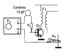
In order to use the device with several types of receivers covering the medium wave range up to the VHF range and having good sensitivity, the injection can be made by simple approximation. For receptors that are less sensitive or that are very uncalibrated the injection should be direct, done in the manner shown in figure 3.

The clip must be connected to the negative side of the power supply and if there is no antenna, the live pole (PP1) must be connected to the input of the stages through a capacitor of 10 to 100 pF ceramic.
The stages should be adjusted according to procedures given in the receiver manufacturers' manuals.
Semiconductors:
Q1 - BC548 or equivalent - NPN general purpose transistor
Q2 - BC558 or equivalent - general purpose PNP transistor
Resistors: (1 / 8W, 5%)
R1 - 22 k ohm - red, red, orange
R2 - 1k ohm - brown, black, red
P1 - 47 k ohm or 100 k ohm - potentiometer
Capacitors:
C1 - 100 nF - ceramic or polyester
C2-47 nF - ceramic or polyester
Several:
L1, L2 - coils - see text
S1 – On/Off switch
B1 - 3V - 2 small batteries
PP1 - Red Probe
G1 - Alligator Clip
Printed circuit board, two battery holder, mounting box, potentiometer knob, wires, solder, etc.


