

Turn on an incandescent light using a match or a cigarette lighter is not an impossible task to the readers who mounted this interesting project.
You can show it as an important piece of a magic show or use it in science works about light and light sensors.
The secret is a LDR or Light Dependent Resistor that "see" the light of a cigarette lighter or other light sources and turns on a SCR (Silicon Controlled Rectifier). The SCR is a solid state switch that can controls large amount of current from low current sources as the LDR used as sensor. The anode load to the SCR circuit is a common incandescent light that glows up when it triggers on.
Glowing up, the lamp produces the necessary feedback to keep the SCR on and also the lamp on.
Turn-off the circuit is another "magic" operation.
Place your hands involving the lamp and, at the same time, puff it. Your friends will think that the puff was turned off the lamp, but really were your hands interrupting the light feedback between the lamp and the LDR that did that.
The circuit should be mounted in a box with the lamp and LDR carefully positioned to get the correct feedback as shown in the figures.
The light produced by the lamp falls into the LDR through a small hole drilled in the box as you see in the figures. This hole should be as small as possible to be imperceptible and avoid your friends to discovery your secret but large enough to allow the light falling on the LDR trigger the circuit. A 1/8 inch hole is enough for the proposed task.
P1 is used to adjust sensvity, compensating the ambient light presence.
Figure 1 shows the schematic diagram of the magic lamp.

The components are monted as shown in figure 2.

Caution! This circuit is directly powered from the AC power line. Avoid exposed junctions or parts that can cause dangerous shock hazards. Use a plastic box or wooden box in your mounting.
The SCR should be mounted on a small heatsink. The LDR is any type and L1 is any incandescent white lamp rated to powers between 25 and 60 watt.
Observe the position of the LDR as the light produced by the incandescent lamp should fall into the LDR surface producing the necessary signal feedback. Figure 3 shows how the LDR and lamp must be placed.
33Figure 3 – LDR placement
Potentiometer P1 is placed in the back as it is not interesting reveal the presence of this component to the "public" in any demonstration.
How to use the magic lamp:
Place the lamp on a table with P1 at the opposite side of the public.
Adjust P1 to get the limiar or pre-trigger point of the circuit. Put your finger on the hole to turn the lamp off during the adjustment phase.
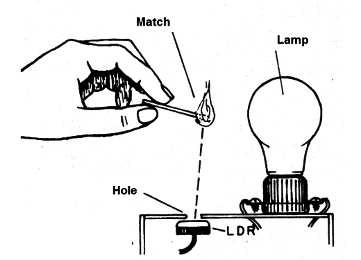
Test the circuit with a match or a cigarette lighter. These light sources should be turned-on at lhe hole side of the mounting to allow their light to fall into the LDR. Figure 4 shows how to turn-on the lamp with a match;
Turn-off the lamps placing your hand near the lamp as described, interrupting the light feedback.
Caution: don't touch the lamp because working after some time it will be very hot.
SCR - MCR106-4 or TIC106-B - SCR or silicon controlled rectifier
LDR - common photo resistor or LDR
L1 - 25 to 60 watt - incandescent lamp rated to 127 VAC
D1 - 1N4002 or equivalent - silicon general purpose diode
R1 - 56,000 ohm, 1/4-watt, 5% - resistor
R2 - 4,700 ohm, 1/4-watt, 5% - resistor
R3 - 10,000 ohm, 1/4-watt, 5% - resistor
R4 – 10,000 ohm, ¼ watt, 5% - resistor (optional)


