

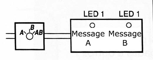
With the circuit shown you can control the blink of three LEDs, placed in a remote panel, using only two connecting wires. With this, we can use the circuit in a signaling system or warning, as shown in Figure 1.
The use of power LEDs greatly facilitates the assembly of the circuit with a great visual effect that is sure to meet the basic objectives of the project.
The circuit is based on the fact that an LED is nothing more than a diode and therefore conducts current in one direction.
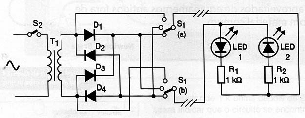
Thus, with the switch in position 1 only LED1 is polarized in the forward direction (given the presence of D1) and only he lights. In position 2 is the LED2 to light and finally in position 3 we make an AC voltage is sent to the remote panel and that the two LEDs light up.
The complete circuit implementation is shown in Figure 2.
The small LEDs and other circuit components can be mounted as shown in Figure 3.
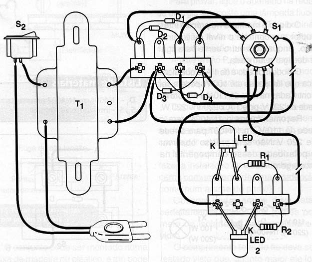
Interconnecting wires between the control station and the receiving station (terminal) can be up to 50 meters in length and should be isolated for safety reasons.
The polarity of the diodes and LEDs should be observed and the transformer is 6 V secondary any current between 150 and 300 mA.
A version of this circuit by replacing the small LED bulbs 6 V x 50 mA is shown in Figure 4.
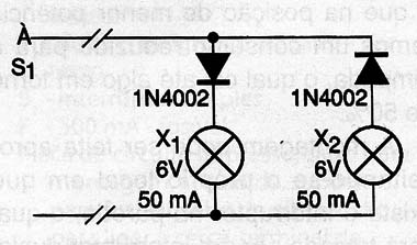
The diodes may be 1N4002 or equivalent for higher voltage.
D1 to D4 - 1N4002 or equivalent - silicon diodes
LED1, LED2 - Common high-brightness LEDs of any color
T1 - with primary transformer according to the local AC power line and secondary 6 V x 150 to 300 mA
S1 – Switch 1 pole x 3 positions
S2 - Single switch
Miscellaneous:
Box mounting, panel for LEDs, wires, solder, power cord, etc.


