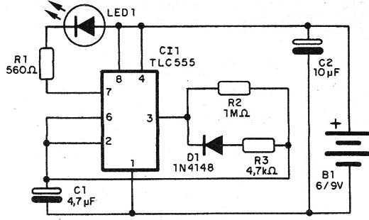
A simple LED flasher can be built with a TLC7555 Timer used as a low-frequency oscillator and drive to an LED.
IC1 runs in a Iow frequency determined by R2IR3 and C1. Frequency is in the range between 0.1 and 5 Hz but you can alter it by changing C1.This capacitor can range from 1 to 10 µF.
Duty cycle is determined by R2/R3 ratio and is important in applications where you need reduction of energy consumed.
Though Figure 1 shows fixed resistors for R2 and R3, you can use trimmer potentiometers if you prefer.
The potentiometers, of course, are handy for altering the frequency and duty cycle of the oscillator.
R1 values depend upon the power supply voltage. With power supplies between 5 and 6 volts, R1 is 470 Ω.
With power supplies between 6 and 9 volts, R1 is 560 or 680 Ω. With power supplies in the range between 9 and 12 volts, R1 must be 1,000 Ω.
The circuit drains only 250 µA from a 6-volt power supply.
Figure 1 shows the schematic diagram for the Micro-Power LED Flasher. At the heart of the circuit is IC1, a 555 timer.

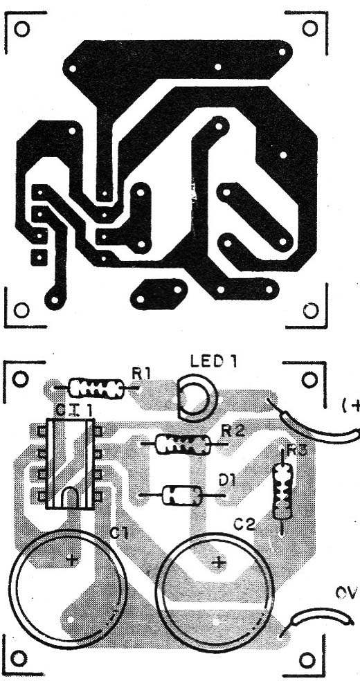
Use the parts placement diagram as a guide when assembling the Micro-Power LED Flasher. Components placement, using a printed circuit board is shown in Figure 2.

Take special care with positions of polarized components, such as the LED and electrolytic capacitor.
After you are sure that you have wired aII the components correctly, put the batteries in the battery holder. The LED should flash.
Micro-Power LED Flasher
IC1 - TLC7555 CMOS Integrated Circuit - Timer
LED1 - Common red, green or yeIIow LED
D1 - 1N914 general purpose silicon diode
R1 - 560 ohm, ¼ W, 5% resistor
R2 - 1,000,000 ohm, ¼ W, 5% resistor
R3 - 4,700 ohm, ¼ W, 5% resistor
C1 - 4,7 µF, 6 WVDC electrolytic capacitor
02 - 10 µF, 12 WVDC eléctrolytic capacitor
B1 - 6 to 12 V AA cells, 9 V battery or power supply
Ideas to Explore
To Iearn more about the circuit and devices:
- Alter R2 and R3 (minimum values are 1,000 Ω for both) and see how the flashing rate changes. Of course, if you want, you can replace R2 and R3 with 1,000,000-ohm trimmer~potentiometers.
- Explain how the astable 555 workà in this circuit.
- Alter C1 in a range between 1 and 100 µF and observe flashing rate alteration. Explain what happens.
- Explain what duty-cycle is.
Science experiments with the circuit:
- LED is a monochromatic light source. You can perform some ex-
periments in optics using this kind of light source.
Chromatic filters can be used in some experiments involving LEDs.Try to use LEDs of different colors (red, yellow, green and, if possible, blue).
Light flashes, as the ones produced by this circuit, can be used in
hypnotic experiments.
The circuit can be used to indicate operation of other electronic
devices. Wired to the power supply of a monitored device, the blinker
LED will indicate its operation. Remember that the theory in this book is specifically related to the associated experiments and projects. This project is designed as an introduction, not as an in-depth treatment of electronics. If you are interested in finding out more about the subjects touched on in this site, several texts can be found for further reading.
Obs. This circuit is part of the author’s book Fun Projects for the Experimenter – TAB Books – 1998


