This circuit uses a one-gate oscillator, with a 4093 CMOS IC, to produce a 50% duty-cycle flasher in two LEDs or a bi-color LED.
The circuit can be powered by a 3 to 12-volt power supply and is useful in several experiments and practical applications. You can use it as part of alarms, warning systems, games, toys, and some scientific experiments, as we will describe here. R2 and R3 values depend upon the power supply voltage, according to the foIIowing table:
| Power Supply | R2, R3 |
| 3 Volts | 220 Ω |
| 5 Volts | 330 Ω |
| 6 Volts | 470 Ω |
| 9 Volts | 820 Ω |
| 12 Volts | 1,000 Ω |
For more output you can use a transistorized output stage driving incandescent Iamps or morethan one LED. Experiments to observe Iight effects on animals and plants can be conducted with this circuit.
P1 and C1 determine flash rate. Flash rate can be adjusted by P1, but C1 also can be altered in a Iarge range of values, according to the application you intend for the device.
Schematic diagram for the Dual-Led Flasher is shown in Figure 1.

One gate of a 4093 IC is used as oscillator and the other two are used as inverters.
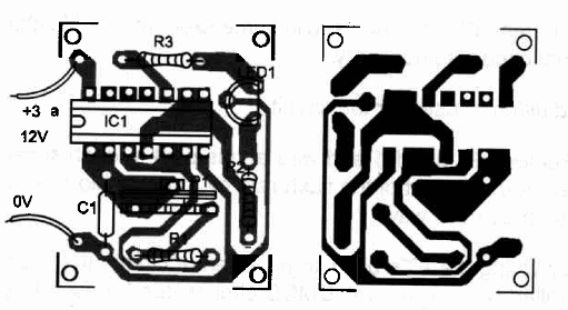
Components placement on a PC board is shown in Figure 2.

You can also use a breadboard or solderless board to mount it as an experimental circuit.
Position of the polarized pieces, such as LEDs, eletrolytics and IC, should be observed.
Dual-Led Flasher
lC1 - 40938 CMOS integrated circuit
LED1 - bi-color or red and green common LEDs (Radio Shack 276-012)
R1 - 100,000 ohm, ¼ W, 5% resistor
R2, R3 - resistor according to power supply voltage - see text
P1 - 1,000,000 ohm potentiometer
C1 - 1 µF, 25 WVDC electrolytic capacitor
ldeas to Explore
To Iearn more about the circuit and devices:
Replace C1 with capacitors in the range between 1 and 47 µF. Observe how higher values alter the flash rate.
Infrared LEDs can be used in some experiments. No change in the original circuit is necessary.
Science and different uses for the circuit
Remove P1 and R1 and wire at this pont a touch sensor or electrodes. You can control the flash rate by touch. A bio-feedback device can be made this way.
By wiring the IC”s pin 1 to an external circuit, the flasher can be controlled by a Iogic IeveL CMOS circuits can be used to control the flasher.
Mount the LEDs in place of the Ienses of a set of eyeglasses. The flash rate can be adjusted to make an hypnotic or relaxing effect. Combine this with a touch sensor and you have an uncommon bio-feedback device. You can also use this circuit to make experíments in circadian rhythms or internal biological clocks, determining how they can be altered by light pulses. Various theories have been proposed about this subject.
Psychiatrists are using phototherapy to help some patients. Can you find some application for the circuit in~this field?
P1 also can be replaced by resistive transducers, such as LDRs or NTCs, to give a light- or temperature-dependent flash-rate circuit. Experiments can be made with conductivity of materials by connecting probes in series with R1. Replace P1 with the probes in this case.
Note: This circuit is part of the author’s book Fun Projects for the Experimenter – TAB Books – 1998


